A kind of h-shaped hollow anti-slide pile

An anti-sliding pile and hollow technology, applied in sheet pile walls, construction, excavation, etc., can solve the problems of increasing the amount of concrete, increasing the cost of the pile body, wasting building materials, etc., to reduce construction costs, reduce construction difficulty, and save money. The effect of concrete

Active Publication Date: 2021-11-02
核工业湖州勘测规划设计研究院股份有限公司
View PDF7 Cites 0 Cited by
  • Summary
  • Abstract
  • Description
  • Claims
  • Application Information

AI Technical Summary

Problems solved by technology

At present, most anti-slide piles are solid piles with circular or rectangular cross-sections. On the one hand, the amount of concrete is increased and the cost of the pile is increased; on the other hand, there is no differential analysis of the stressed parts of the pile. A certain amount of waste of building materials

Method used


Image

  • A kind of h-shaped hollow anti-slide pile
  • A kind of h-shaped hollow anti-slide pile
  • A kind of h-shaped hollow anti-slide pile

Examples


Embodiment 1

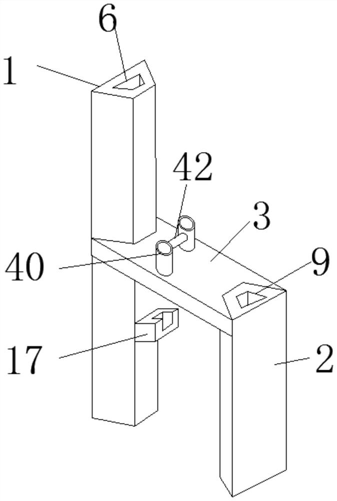
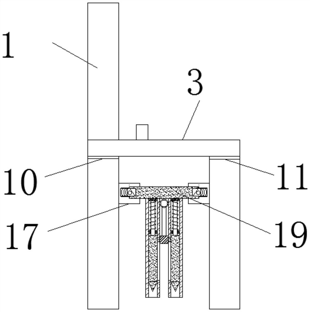
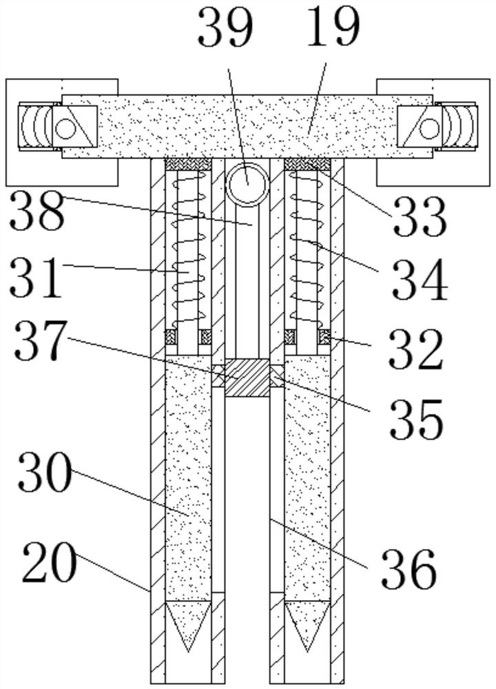
[0032] see Figure 1-12 , an h-shaped hollow anti-slide pile according to an embodiment of the present invention, comprising a front pile 1 and a rear pile 2, a beam 3 is connected between the front pile 1 and the rear pile 2, and the front pile 1 includes a pile Front-end-4 and pile rear-end-5, the thickness of pile front-end-4 exceeds pile rear-end-5, and hollow hole-6 is arranged between described pile front-end-4 and described pile rear-end-5, and described rear pile 2 includes pile front end 2 7 and pile rear end 2 8, the thickness of pile front end 2 7 is greater than pile rear end 2 8, and a hollow hole 2 9 is arranged between the pile front end 2 7 and the pile rear end 2 8, so The front pile 1 is provided with a front pile projection 10 near the crossbeam 3, and the rear pile 2 is provided with a rear pile projection 11 near the crossbeam 3. The front pile projection 10 and the rear pile projection Blocks 11 are located below the beam 3, the bottoms of the front pile...

Embodiment 2

[0037] see Figure 6-7 , the included angles between the pile front end 4 and the hollow hole 6 are both 50°-60°, and the included angles between the pile front end 2 7 and the hollow hole 9 are both 50°-60°.

[0038] In order to facilitate the understanding of the above-mentioned technical solution of the present invention, the working principle or operation mode of the present invention in the actual process will be described in detail below.

[0039] In actual application, determine the position of the front pile 1, use excavators and rock drills to excavate the rock and soil in an isosceles trapezoidal shape, and use a pump to continuously pump out the water in the hole during the hole digging process, and ensure that the bottom of the hole is clean and clean , so as not to affect the construction of the pile, the bottom of the front pile is respectively pierced through the sliding body 14, the sliding belt 12 and finally stretched into the sliding bed 13, and hammered to ...


PUM


Abstract

The invention discloses an h-shaped hollow anti-sliding pile, which comprises a front pile and a rear pile, a beam is connected between the front pile and the rear pile, and the front pile includes a pile front end and a pile rear end. A hollow hole 1 is provided between the front end 1 of the pile and the rear end 1 of the pile. The rear pile includes a front end 2 and a rear end 2 of the pile. Hole 2, the front pile is provided with a front pile bump near the crossbeam, and the rear pile is provided with a rear pile bump near the crossbeam, and both the front pile bump and the rear pile bump are located Below the crossbeam, the bottoms of the front pile and the rear pile run through the slide belt and are located in the slide bed, the tops of the front pile and the rear pile are located in the slide body, and a steel bar is embedded inside the front pile. , the inside of the back pile is embedded with two steel bars. Beneficial effects: the soil arch effect of the soil between the piles is fully brought into play, and the anti-slide pile is more conducive to supporting the landslide.

Description

technical field [0001] The invention relates to the technical field of civil engineering and geotechnical engineering, in particular to an H-shaped hollow anti-slide pile. Background technique [0002] In the field of landslide control, anti-slide piles are widely used in landslide support, but due to the shortcomings of ordinary anti-slides such as insufficient bending resistance and low overall stiffness. The predecessors have taken different ground measures to improve the anti-sliding performance of the anti-slide pile, such as increasing the cross-sectional area of ​​the single pile or making the pile body into a trapezoid to increase the compressive performance of the pile body, but this increases the strength of the concrete. The dosage increases the project cost. [0003] However, when dealing with large landslides, the shortcomings of the single pile's insufficient anti-sliding ability are undoubtedly exposed. The predecessors used anchor cable anti-slide piles and...

Claims


Application Information

Patent Timeline
Patent Type & Authority Patents(China)
IPC IPC(8): E02D17/20E02D5/30
CPCE02D5/30E02D17/20E02D17/207E02D2200/1657E02D2600/20
Inventor 马云长朱伟马飞跃邓世平徐清清戚鹏英张菊锋
Owner 核工业湖州勘测规划设计研究院股份有限公司
Why Eureka
Try Eureka