Scab remover for burn department

A coupling and screw technology, which is applied to surgical cutting instruments, surgical scissors, etc., can solve the problems of poor use effect, complicated operation, and vulnerable skin.

Active Publication Date: 2021-09-10
QINGDAO CITY CHENGYANG DISTRICT PEOPLES HOSPITAL
View PDF0 Cites 0 Cited by
  • Summary
  • Abstract
  • Description
  • Claims
  • Application Information

AI Technical Summary

Problems solved by technology

[0004] The various scab removers in the prior art either have high production costs and are not easy to promote, or are complicated to operate and use, and the use effect is not good, and they are easy to damage normal skin when removing scabs, which brings great benefits to both doctors and patients. inconvenient

Method used


Image

  • Scab remover for burn department
  • Scab remover for burn department
  • Scab remover for burn department

Examples


Embodiment 1

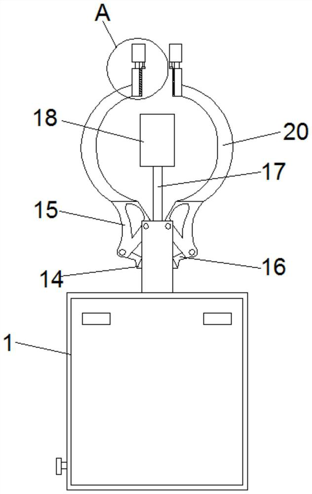
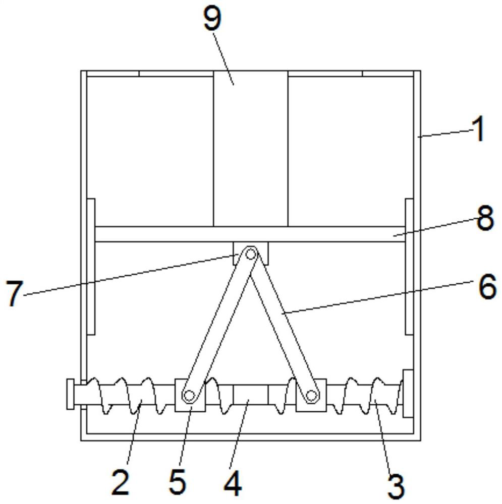
[0034] see Figure 1-9According to an embodiment of the present invention, a scab remover for burns department includes a storage box 1, a screw one 2 and a screw two 3 are arranged inside the storage box 1, and the screws on the first screw 2 and the second screw 3 are The screw thread is a reverse thread, and the screw one 2 and the screw two 3 are connected through a coupling 4, and the screw one 2 and the screw two 3 are screwed on the outside to be provided with a slide block 5, and the The slide block 5 is provided with a movable shaft one, and the movable shaft one is movably connected with a support rod 6, and the support rod 6 is far away from the movable shaft one end is sleeved on the movable shaft two, and the movable shaft Two are fixed on the fixed block 7, and the fixed block 7 is fixed on the bottom of the lifting seat 8, and the adjusting column 9 is fixed on the lifting seat 8, and the interior of the adjusting column 9 is provided with a cavity-10, and the c...

Embodiment 2

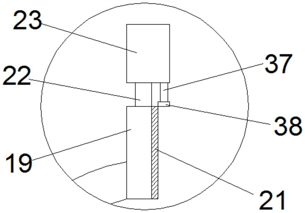
[0036] see image 3 and Figure 4 , for the screw one 2, the end of the screw one 2 away from the coupling 4 penetrates through the storage box 1 and extends to the outside of the storage box 1 with an adjustment knob. For the storage box 1 , a slide rail 1 is installed symmetrically on the inner wall of the storage box 1 , and the lifting base 8 is matched with the slide rail 1 . For the adjustment column 9, the inside of the adjustment column 9 is fixed with a baffle plate 2 41, and the screw rod 13 runs through the baffle plate 2 41, and the adjustment knob is provided to facilitate manual operation adjustment; There is a slide rail 1, which cooperates with the lifting seat 8 to carry out lifting adjustment; the baffle plate 2 41 is provided to play the role of limit support.

Embodiment 3

[0038] see Figure 7 and Figure 8 For the storage box 1, the top of the storage box 1 is provided with a storage cavity, the inside of the storage cavity is provided with a matching dustproof cover 42, and both sides of the storage cavity are provided with a cavity three 40 and an empty space. Cavity 2 43, motor 3 45 is installed symmetrically and fixedly in the cavity 3 40, the output end of the motor 3 45 is connected with the screw rod 2 46, and the outer screw connection of the screw rod 2 46 is provided with an adjustment block 49 . As for the second cavity 43 , a sliding rod 47 is fixed inside the second cavity 43 , and a sliding sleeve 48 is sheathed on the outer side of the sliding rod 47 . For the storage cavity, two slide rails are provided between the storage cavity and the third cavity 40 and the second cavity 43, and the inside of the second slide rail is provided with a matching movable block 44. Both sides of the movable block 44 are fixedly connected with t...


PUM


Abstract

The invention discloses a scab remover for burns, which comprises a storage box. A screw 1 and a screw 2 are arranged inside the storage box. The threads on the screw 1 and the screw 2 are reverse threads. The shafts are connected with each other, the outer sides of screw one and screw two are threadedly connected with sliders, and movable shaft one is arranged on the sliders, and a support rod is movably connected on the movable shaft one, and the support rod is sleeved at one end away from the movable shaft On the movable shaft 2, the movable shaft 2 is fixed on the fixed block, and the fixed block is fixed on the bottom of the lifting seat. An adjusting column is fixed on the lifting seat, and a cavity 1 is arranged inside the adjusting column, and both sides of the cavity 1 are provided with limited positions. Groove, the inner top of cavity one is fixedly installed with motor one, and the output end of motor one is connected with screw mandrel one, and screw mandrel one outer thread connection is provided with lifting block, and lifting block matches with limit groove. Beneficial effects: manpower is saved, operation and use are simple, and scabs are removed thoroughly.

Description

technical field [0001] The invention relates to a scab remover, in particular to a scab remover for burn departments. Background technique [0002] Usually after burns or skin bleeding, due to the coagulation of platelets, scabs will form on the skin, and small scabs will fall off by themselves in time, but tools are usually needed for more serious burns or large-area burns. There is no more suitable special tool for processing. [0003] At present, most of the clinical treatment methods for deep second-degree burn wounds use manual scab removal. The commonly used methods include: "roller type dermatome" scraping scab and wound scraping or steel wool scab. The former has become a routine or traditional method. However, although the "roller type dermatome" commonly used in clinical practice is more precise, due to the scab removal technique of the operator, the angle between the blade and the wound surface, the force of the operator, the sharpness and bluntness of the blade,...

Claims


Application Information

Patent Timeline
Patent Type & Authority Patents(China)
IPC IPC(8): A61B17/3201A61B17/3205
CPCA61B17/3201A61B17/3205
Inventor 韩晓春
Owner QINGDAO CITY CHENGYANG DISTRICT PEOPLES HOSPITAL
Why Eureka
Try Eureka