Laser, mode locking state monitoring method and mode locking state monitoring device

A state monitoring and laser technology, applied in the laser field, can solve problems such as affecting the judgment result of the mode locking state, poor mode locking state monitoring effect, unstable pulse count, etc., to improve the mode locking state monitoring effect, avoid environmental impact, and calculate fast effect

Pending Publication Date: 2021-01-26
北京卓镭激光技术有限公司
View PDF6 Cites 0 Cited by
  • Summary
  • Abstract
  • Description
  • Claims
  • Application Information

AI Technical Summary

Problems solved by technology

[0004] The above mode-locking state judgment scheme needs the actual number of pulses in the counting period, not only the detection process is complicated, but the detection speed is slow; and the pulse co

Method used


Image

  • Laser, mode locking state monitoring method and mode locking state monitoring device
  • Laser, mode locking state monitoring method and mode locking state monitoring device
  • Laser, mode locking state monitoring method and mode locking state monitoring device

Examples


Example Embodiment

[0095] Example 1.

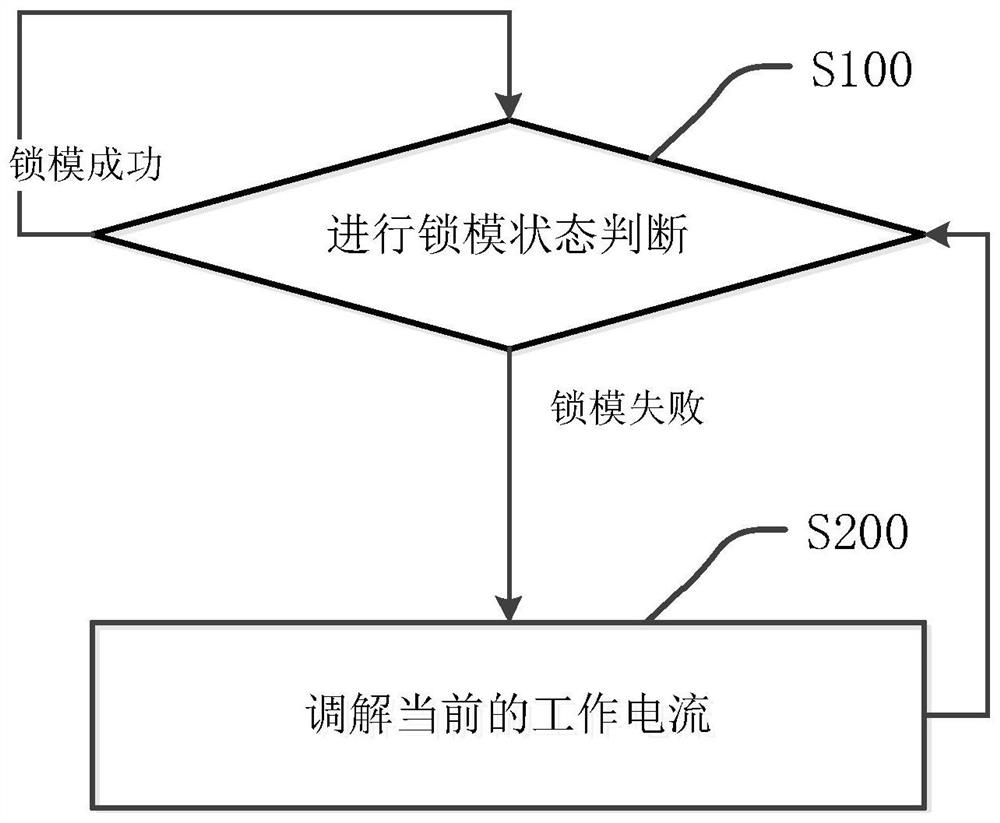
[0096] refer to figure 1 , as an implementation of a mode-locking state monitoring method, a mode-locking state monitoring method is applied to a laser or a laser detection device to monitor the mode-locking state of a laser, comprising the following steps:

[0097] Step S100: Judgment of the mode locking status (mode locking status judging process); if the mode locking status is that the mode locking is successful, execute step S100 and continue to judge the mode locking status; otherwise, execute step S200.

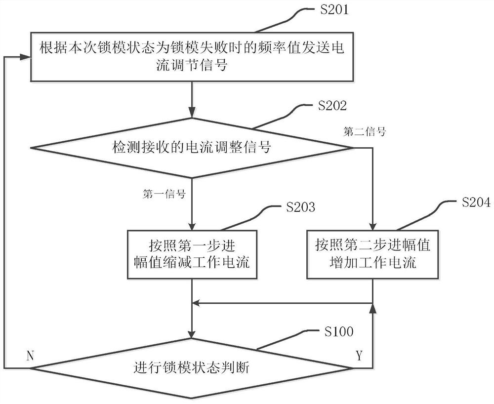
[0098] Step S200, adjust the current working current, and then execute step S100, it can be seen that the mold locking process includes steps S100 and S200.

[0099] It should be noted that when the laser is started or the mode-locking state is mode-locking failure, step S200 will be triggered to start execution, so as to ensure that the restarted laser or the mode-locking failed laser is in the mode-locking success state.
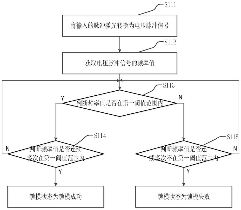
[0100] In this example,...

Example Embodiment

[0130] Example 2.

[0131] Compared with Embodiment 1, this implementation introduces the first preset threshold and the second preset threshold, and uses the first preset threshold or the second preset threshold to realize the judgment that the frequency value is within or not within the range of the first threshold multiple times in a row , each time the mode-locking state is judged, the number of times the frequency value is continuously within or not within the first threshold range must reach the first preset threshold or the second preset threshold before the mode-locking state is judged as successful or failed. This ensures that the mode-locking state is stable at this time, effectively improving the reliability of the judgment result of the mode-locking state, thereby improving the stability of the mode-locking state monitoring system. The method for judging the mode-locking state provided by this embodiment, such as Figure 4 shown, including the following steps:

...

Example Embodiment

[0141] Example 3.

[0142]Compared with Embodiment 1, this embodiment introduces the first identifier, and uses the first identifier to realize the judgment of whether the frequency value is within the first threshold range for multiple consecutive times, and the first identifier includes successful preparation and failure preparation status Two states; when the frequency value is within the first threshold range, the first identifier is set as a successful preparation state; when the frequency value is not within the first threshold range, the first identifier is set as a failure preparation state; this implementation For example, each time the frequency value is judged whether it is in or out of the first threshold range multiple times in a row, the frequency value can be obtained twice at most, but it can ensure that the frequency value is in or out of the first threshold range for at least two consecutive times. Under the premise of the reliability of the results of the mo...


PUM


Abstract

The invention relates to a laser and a mode locking state monitoring method and device, and the method comprises the steps: executing a mode locking state judgment flow when the mode locking state ismode locking success; if the mode locking state is mode locking failure, executing a mode locking process; wherein the mode locking process comprises the steps of adjusting a working current, and thenexecuting a mode locking state judgment process; the mode locking state judgment process comprises the step of judging the mode locking state according to the frequency value of the pulse laser; andthe pulse laser is collected at an output port of a laser or a seed light source of the laser, and the judgment logic for judging the mode locking state according to the frequency value of the pulse laser is as follows: if the frequency value is within a first threshold range and is continuously within the first threshold range for multiple times, and the mode locking state is judged to be that the mode locking is successful; and if the frequency value is not within a first threshold range and is not within the first threshold range for multiple consecutive times, the mode locking state is judged to be that the mode locking fails. The method has the effects of quickly detecting lock loss and quickly recovering mold locking.

Description

technical field [0001] The present application relates to the field of laser technology, in particular to a method and device for monitoring the state of a laser and mode-locking. Background technique [0002] Ultrashort pulse laser has extremely narrow pulse width, ultra-high peak power and ultra-high repetition rate, and has been widely used in medical, scientific research, industry and other fields. In order to obtain ultra-short pulse laser, it is necessary to perform mode-locking operation on the laser, so that the phases of multiple independent oscillation longitudinal modes with different oscillation frequencies in the laser resonator can be fixed, and a regular ultra-short pulse sequence can be obtained. Ultrashort pulse laser obtained by coherent superposition of oscillation longitudinal modes. [0003] In practical applications, in order to ensure that the laser outputs stable ultrashort pulse laser, it is necessary to monitor the mode-locking state of the laser i...

Claims


Application Information

Patent Timeline
IPC IPC(8): H01S3/11H01S3/00
CPCH01S3/0014H01S3/11H01S3/1109
Inventor 于海波
Owner 北京卓镭激光技术有限公司
Why Eureka
Try Eureka