A Calculation Method of Resistance of Impeller Centrifugal Ventilator

A technology of resistance calculation and ventilator, applied in the direction of instrument, design optimization/simulation, testing of machine/structural components, etc., can solve the problems of complex calculation process, poor applicability, loss of reference value of test results, etc. The effect of strong applicability, shortening computing cost and computing cycle

Active Publication Date: 2022-05-06
AECC SHENYANG ENGINE RES INST
View PDF4 Cites 0 Cited by
  • Summary
  • Abstract
  • Description
  • Claims
  • Application Information

AI Technical Summary

Problems solved by technology

[0003] However, the simulation analysis method requires steps such as model establishment, meshing and simulation analysis. The calculation process is relatively complicated, the cycle is long, and only discrete points under fixed conditions can be obtained. It requires a lot of manpower and time, and the efficiency is low.
However, the test fitting method measures the resistance value of the ventilator through the test piece on the tester. It needs to invest in the test piece, test equipment and test personnel, and can only obtain discrete resistance points under fixed conditions. The fitting accuracy is closely related to the accuracy of the test equipment, the skills of the test personnel and the selection of test points, the cost is high and the efficiency is low; if the structure of the ventilator changes, the test results will lose their reference value
[0004] At present, in the scheme design stage of the aeroengine lubrication system, it is necessary to calculate and evaluate up to dozens of state points in the typical section of the engine, and it is necessary to continuously adjust and improve the system scheme. The above two methods are costly, long-term and applicable. Poor performance, no longer meet the design requirements of modern engine ventilation system

Method used


Image

  • A Calculation Method of Resistance of Impeller Centrifugal Ventilator
  • A Calculation Method of Resistance of Impeller Centrifugal Ventilator
  • A Calculation Method of Resistance of Impeller Centrifugal Ventilator

Examples


Embodiment Construction

[0035] In order to make the purpose, technical solution and advantages of the application more clear, the technical solution in the embodiment of the application will be described in more detail below in conjunction with the drawings in the embodiment of the application.

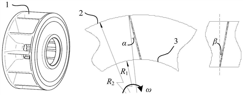
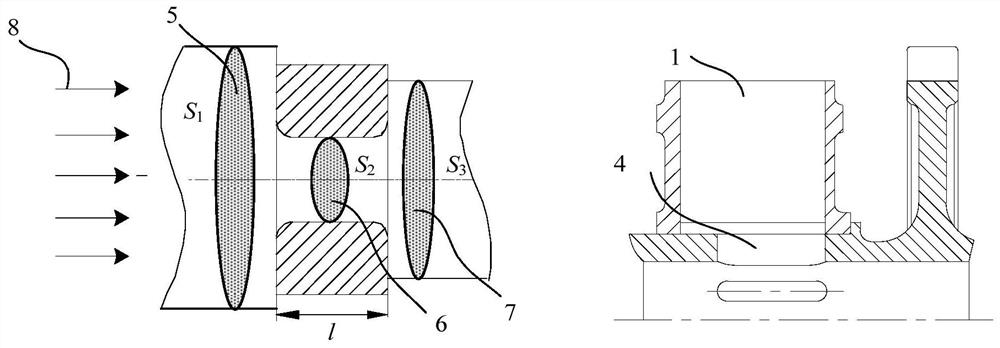
[0036] The method for calculating the resistance of the impeller-type centrifugal ventilator provided by the present application mainly includes the calculation of the resistance of the impeller unit, the calculation of the resistance of the aperture unit, and the calculation of the overall resistance of the impeller-type centrifugal ventilator.

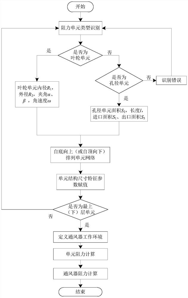
[0037] Such as figure 1 As shown, the impeller centrifugal ventilator resistance calculation method provided by the application includes the following steps:

[0038] Step 1: Build the resistance feature unit network architecture

[0039] According to the structure of the impeller centrifugal ventilator, the arrangement and connection of the impeller unit and the ...


PUM


Abstract

The application provides a method for calculating the resistance of an impeller centrifugal ventilator, including: determining the impeller unit and aperture of the impeller centrifugal ventilator according to the structure of the impeller centrifugal ventilator and the flow direction of the airflow passing through the impeller centrifugal ventilator According to the arrangement of units, construct the network framework of the resistance characteristic unit; determine the parameter value of the corresponding resistance characteristic unit according to the structural parameters and operating parameters of the resistance characteristic unit; determine the working environment of the impeller type centrifugal ventilator; according to the working environment Calculate the impeller element resistance and aperture element resistance and the overall resistance of an impeller centrifugal fan with multiple impeller elements and aperture elements for the parameter values ​​of . The method provided in this application can directly obtain the theoretical expression of the resistance of the impeller centrifugal ventilator through the construction of a network structure based on the structural characteristics and dimensions of the impeller centrifugal ventilator. The calculation method is simple and efficient, and can be applied to the resistance under all working conditions calculate.

Description

technical field [0001] The application belongs to the technical field of impeller-type centrifugal ventilators, and in particular relates to a method for calculating resistance of an impeller-type centrifugal ventilator. Background technique [0002] The impeller centrifugal ventilator is the most widely used ventilator in aero-engines, and its resistance characteristic is the most important design index of the lubrication ventilation system. At present, the methods for obtaining the resistance of impeller centrifugal ventilators mainly include simulation analysis method and test fitting method. The simulation analysis method mainly uses computer software to simulate the operating conditions of the impeller centrifugal ventilator to obtain its resistance characteristics. It needs to use CAD software for modeling, mesh division software for mesh division, and CFD software for simulation analysis. The resistance of the impeller centrifugal ventilator at a specific speed and e...

Claims


Application Information

Patent Timeline
Patent Type & Authority Patents(China)
IPC IPC(8): G01M13/00G01M15/00G06F30/20
CPCG01M13/00G01M15/00G06F30/20
Inventor 荆帅谷俊韩金在刘向坤张鹏发王铭章董云苏常青
Owner AECC SHENYANG ENGINE RES INST
Why Eureka
Try Eureka