

Liftable wind power generation street lamp for road
A lift-type, street lamp technology, applied in wind power generation, wind turbines, wind turbine combinations, etc., can solve the problems of consumption, street lamps can not play the role of lighting, can not achieve energy saving, etc., to reduce energy consumption and power generation. Good, damage-avoiding effect
- Summary
- Abstract
- Description
- Claims
- Application Information
AI Technical Summary
Problems solved by technology
Method used
Image

Examples
Embodiment 1
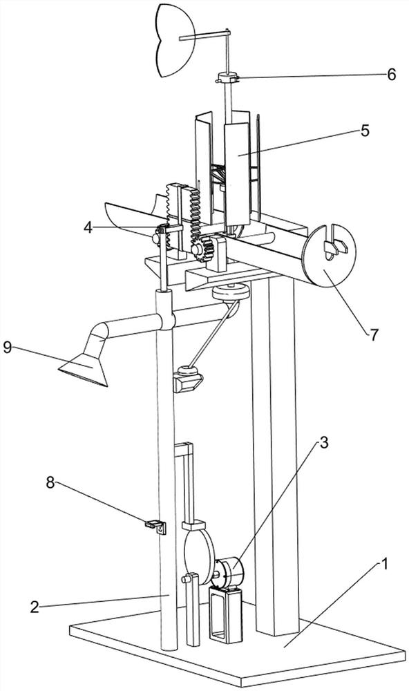
[0065] A kind of liftable wind power generating circuit lamp for road, such as figure 1 As shown, it includes a base plate 1, a lamp frame 2, a lifting mechanism 3, a power generating mechanism 5 and a street lamp 9. A lamp frame 2 is provided on the front side of the top of the base plate 1, and a power generating mechanism 5 is provided on the lamp frame 2. In the middle of the top of the base plate 1, there is a The lifting mechanism 3 and the front end of the lamp holder 2 are provided with a street lamp 9 .
[0066] Such as figure 2 As shown, the lifting mechanism 3 includes a first support seat 31, a servo motor 32, a transmission rod 33, a first support frame 34, a cam 35 and a connecting frame 36, and the first support seat 31 is arranged in the middle of the bottom plate 1 top. The top of the seat 31 is provided with a servo motor 32, the front side of the top of the bottom plate 1 is provided with a first support frame 34, and the upper side of the first support fr...
Embodiment 2
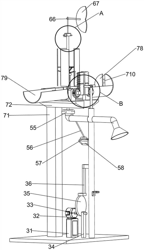
[0070] On the basis of Example 1, such as Figure 4 with Image 6 Shown, also comprise link mechanism 4, link mechanism 4 includes ejector rod 42, top seat 43, rotating fixed seat 44, first support rod 45 and first connecting rod 46, and the middle part of rotating rod 59 is slidably provided with Top seat 43, top seat 43 top is provided with rotating fixed seat 44, and rotated fixed seat 44 links to each other with stretching out slide bar 53, and the uniform rotation type of rotating fixed seat 44 outsides is provided with first support bar 45, and connecting frame 36 tops are provided with the first support bar 45. A connecting rod 46, the rear end of the first connecting rod 46 is provided with a push rod 42, and the push rod 42 cooperates with the rotating fixed seat 44.
[0071] When there is a strong wind, the staff can start the servo motor 32 to work, the output shaft of the servo motor 32 rotates to drive the transmission rod 33 to rotate, the transmission rod 33 ro...
PUM
 Abstract
Description
Claims
Application Information