Copper sheet stamping equipment for electrical switch base production

A technology of stamping equipment and electrical switch, applied in the field of stamping equipment, can solve the problems of high labor intensity and low cutting efficiency, and achieve the effect of reducing labor intensity and improving cutting efficiency

Active Publication Date: 2021-04-06
台州市焱迪企业有限公司
View PDF30 Cites 4 Cited by
  • Summary
  • Abstract
  • Description
  • Claims
  • Application Information

AI Technical Summary

Problems solved by technology

[0005] In order to overcome the disadvantages of high labor intensity and relatively low cutting efficiency of manually cutting copper plates into copper sheets, the technical problem to be solved by the present invention is to provide a method that can automatically cut copper plates into copper sheets, reduce labor intensity, Copper sheet stamping equipment for electrical switch housing production that can improve cutting efficiency

Method used


Image

  • Copper sheet stamping equipment for electrical switch base production
  • Copper sheet stamping equipment for electrical switch base production
  • Copper sheet stamping equipment for electrical switch base production

Examples


Embodiment 1

[0030] A copper stamping equipment for the production of electrical switch sockets, such as Figure 1 to Figure 3 As shown, it includes a bottom plate 1, a tripod 2, a driving mechanism 3 and a stamping mechanism 4. The front and rear sides of the bottom of the bottom plate 1 are connected with a tripod 2, the top of the bottom plate 1 is equipped with a driving mechanism 3, and the driving mechanism 3 is equipped with a stamping mechanism. Institution 4.

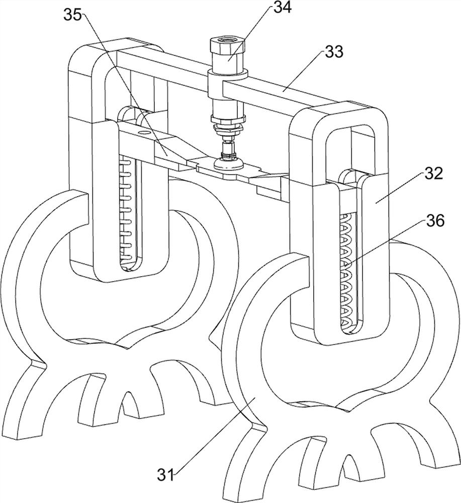
[0031] The drive mechanism 3 includes a first support frame 31, a first guide rail frame 32, a mounting frame 33, a cylinder 34, a sliding push frame 35 and a first return spring 36, and two first supports are symmetrically connected front and rear on the left side of the top of the bottom plate 1. Frame 31, the first support frame 31 is connected with the first guide rail frame 32, is connected with the mounting frame 33 between the inner surface of two first rail frames 32, is equipped with cylinder 34 on the mounting fra...

Embodiment 2

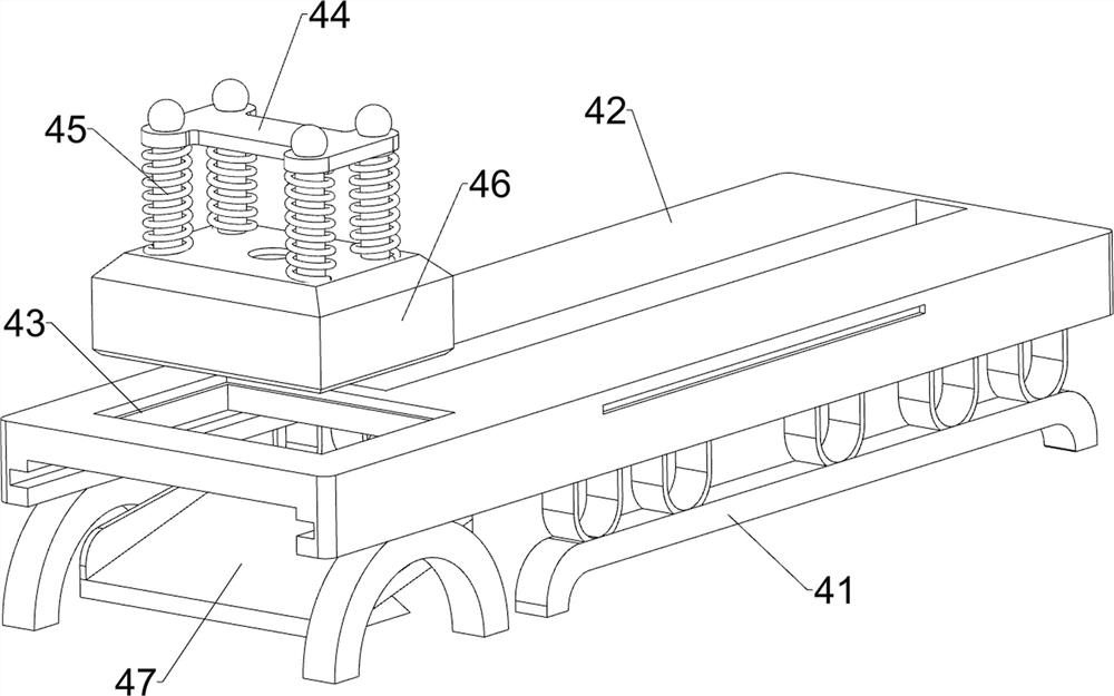
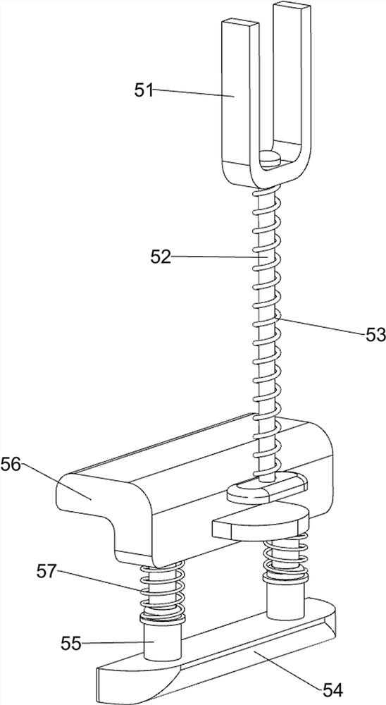
[0035] On the basis of Example 1, such as figure 1 and Figure 4 As shown, a limit mechanism 5 is also included, and the limit mechanism 5 includes a first connecting frame 51, a sliding push rod 52, a first support spring 53, a mounting block 54, a first folding rod 55, a clip block 56 and a second support The spring 57, the front and rear sides of the sliding push frame 35 bottom are all connected with the first connecting frame 51, the first connecting frame 51 is slidably connected with the sliding push rod 52, and the sliding pushing rod 52 is connected with the first connecting frame 51. The first support spring 53, the left part of the front and rear sides of the placement table 42 is connected with the mounting block 54, and the top of the mounting block 54 is symmetrically connected with two first folding rods 55, between the tops of the two first folding rods 55 A clip block 56 is connected, and a second supporting spring 57 is connected between the clip block 56 an...

Embodiment 3

[0038] On the basis of Example 2, such as figure 1 and Figure 5 As shown, a feeding mechanism 6 is also included, and the feeding mechanism 6 includes a second connecting frame 61, a slide block 62, a pushing frame 63 and a handle 64, and two sliding blocks 62 are connected in front and rear symmetrical slides in the placing table 42. , A second connecting frame 61 is connected between the inner surfaces of the two slide blocks 62 , a pushing frame 63 is connected to the top of the second connecting frame 61 , and a handle 64 is connected to the right side of the pushing frame 63 .

[0039] The copper plate 9 is placed on the left side of the pusher frame 63, when the copper plate 9 is to be moved to the left, the handle 64 can be pushed to the left so that the pusher frame 63 moves to the left, and the pusher frame 63 can push the copper plate to the left 9 moves to the left; the copper plate 9 can be moved by the feeding mechanism 6 in this way.

[0040] Such as figure 1...


PUM


Abstract

The invention relates to stamping equipment, in particular to copper sheet stamping equipment for electrical switch base production. The copper sheet stamping equipment for electrical switch base production can automatically cut a copper plate into copper sheets and can reduce labor intensity and improve cutting efficiency. The copper sheet punching equipment for electrical switch base production comprises: a bottom plate, wherein the two sides of the bottom of the bottom plate are each connected with foot stands; and a driving mechanism, wherein the driving mechanism is installed at the top of the bottom plate, and a stamping mechanism is installed on the driving mechanism. The stamping mechanism can be driven to work through the driving mechanism, and the copper plate can be stamped into the copper sheets through the stamping mechanism; and therefore, the effects that the copper plate can be automatically cut into the copper sheets, the labor intensity can be reduced, and the cutting efficiency can be improved are achieved.

Description

technical field [0001] The invention relates to a stamping equipment, in particular to a copper sheet stamping equipment for electric switch base production. Background technique [0002] Copper sheets are needed in the production of electrical switch seats. Copper sheets are cut from copper sheets. At present, cutting copper sheets into copper sheets is generally done manually. When cutting manually, first draw a mark on the copper sheet with a pen. Then cut along the marks with a hand-held cutting knife to cut the copper plate into individual copper sheets. This cutting method takes more time and energy, and is labor-intensive, and the cutting efficiency is relatively low. During the cutting process, accidentally hand Easily cut. [0003] Therefore need to research and develop a kind of copper sheet stamping equipment that can automatically cut copper plate into copper sheet, can reduce labor intensity, can improve cutting efficiency, and is used for the production of ele...

Claims


Application Information

Patent Timeline
Patent Type & Authority Applications(China)
IPC IPC(8): B21D22/02B21D43/00B21D43/04B21D43/28B21D45/02
CPCB21D22/02B21D43/28B21D43/003B21D43/04B21D45/02
Inventor 欧阳维明
Owner 台州市焱迪企业有限公司
Why Eureka
Try Eureka