Foam material transferring mechanism

A transfer mechanism and foam technology, applied in the direction of conveyor objects, transportation and packaging, can solve problems such as easy failure, save material waste, save robot investment, and improve production efficiency.

Pending Publication Date: 2021-05-28
GREE ELECTRIC APPLIANCES WUHAN +1
View PDF0 Cites 0 Cited by
  • Summary
  • Abstract
  • Description
  • Claims
  • Application Information

AI Technical Summary

Problems solved by technology

[0005] The invention provides a foam material transfer mechanism to solve the problem that the sucker-type material is prone to failure, improve production efficiency, and save robot input and material waste

Method used


Image

  • Foam material transferring mechanism

Examples


Embodiment Construction

[0024] The present invention will be further described in detail below in conjunction with the accompanying drawings and specific embodiments. It should be noted that, as long as there is no conflict, each embodiment and each feature in each embodiment of the present invention can be combined with each other, and the formed technical solutions are all within the protection scope of the present invention.

[0025] The parts not mentioned in the present invention can be realized by adopting or referring to the prior art.

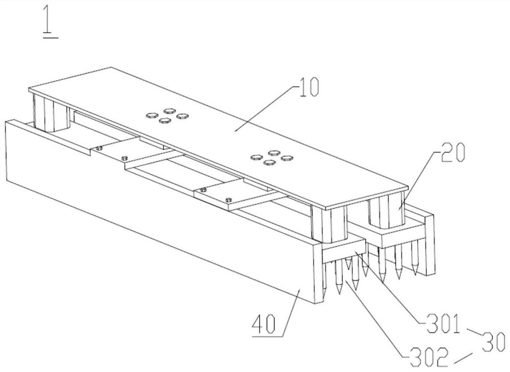
[0026] Such as figure 1 As shown, a foam material transfer mechanism is provided. The foam material transfer mechanism 1 of the present invention includes a base 10, a first driver 20, a second driver (not shown in the figure), a photosensitive element (not shown in the figure) out) and the foam material fetching part 30, the first driving part 20, the second driving part and the foam material fetching part 30 are fixed on the base 10, and the photosensitive ...


PUM

PropertyMeasurementUnit
diameteraaaaaaaaaa

Abstract

The invention provides a foam material transferring mechanism. The foam material transferring mechanism comprises a base, a first driving part, a second driving part, a photosensitive element and a foam material taking and transferring part, wherein the first driving part, the second driving part and the foam material taking and transferring part are fixed to the base; and the photosensitive element controls the first driving part to drive the foam material taking and transferring part to take foam materials in the vertical direction and controls the second driving part to drive the foam material taking and transferring part to transfer the taken foam materials in the horizontal direction and the vertical direction. According to the foam material transferring mechanism, an air cylinder, the photosensitive element, steel needles and a foam baffle are utilized, the structure that the small air cylinder is matched with a high-density steel needle base is adopted, the problem that faults are likely to happen during suction cup type material taking is solved, and robot input and material waste are reduced while the production efficiency is improved.

Description

technical field [0001] The invention relates to a material transfer device, in particular to a foam material transfer mechanism. Background technique [0002] The split air conditioner is a kind of air conditioner. The split air conditioner is to divide the air conditioner into two parts: the indoor unit and the outdoor unit. The indoor unit and the outdoor unit are respectively installed indoors and outdoors. Wire connection, place the noisy compressor, axial fan, etc. in the outdoor unit; install the electrical control circuit components and indoor heat exchanger and other indoor indispensable parts in the indoor unit; An air conditioner composed of an outdoor unit is called a split air conditioner. Split-type air conditioner indoor units include wall-mounted, vertical cabinet, ceiling, embedded, and floor-standing. [0003] In the production of split internal units, the foam is often packaged by automatic packaging, and the foam is taken out of the special tooling vehic...

Claims


Application Information

Patent Timeline
Patent Type & Authority Applications(China)
IPC IPC(8): B65G47/90
CPCB65G47/90
Inventor 沈骞刘威王亮杨先俊蒋晓波杨保
Owner GREE ELECTRIC APPLIANCES WUHAN
Why Eureka
Try Eureka