Structure of portable energy storage power station

An energy storage power station, portable technology, applied in the direction of structural parts, electrical equipment structural parts, circuits, etc., can solve the problems of the portable energy storage power station can not be cooled in time, inconvenient to carry, etc., to improve stability and service life , The internal stability of the structure, the effect of preventing movement

Active Publication Date: 2021-07-30
深圳市恒泰能源科技有限公司
View PDF9 Cites 1 Cited by
  • Summary
  • Abstract
  • Description
  • Claims
  • Application Information

AI Technical Summary

Problems solved by technology

[0005] The present invention provides a structure of a portable energy storage power station, which is used to solve the technical problems that the portable energy storage power station proposed in the above background technology cannot be cooled in time and is inconvenient to carry

Method used


Image

  • Structure of portable energy storage power station
  • Structure of portable energy storage power station
  • Structure of portable energy storage power station

Examples


Embodiment 1

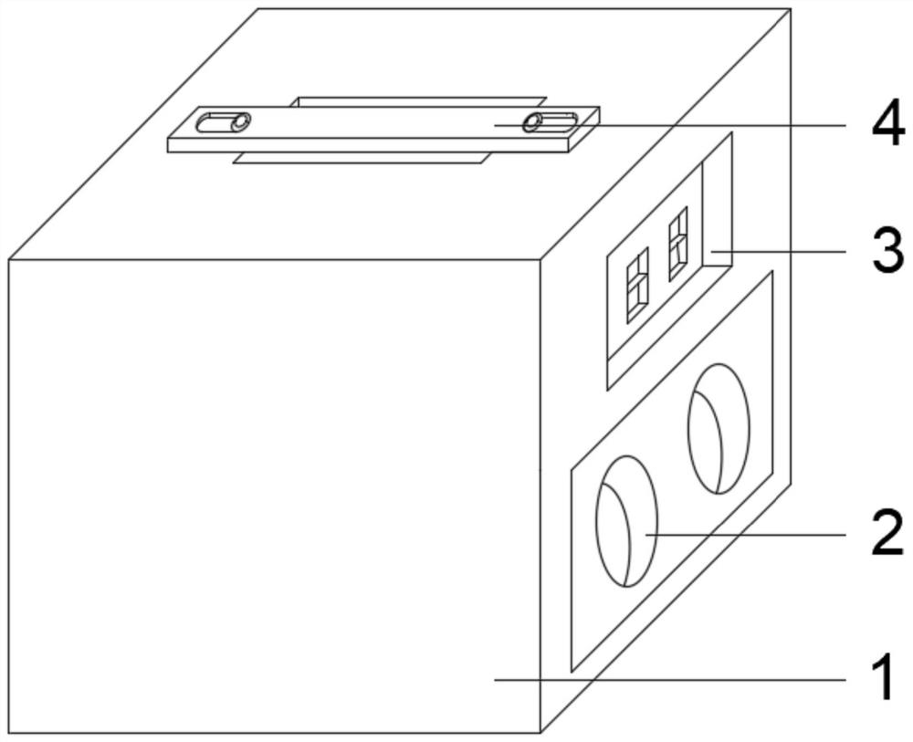
[0074] see figure 1 , the present invention provides a technical solution:

[0075] A structure of a portable energy storage power station, comprising:

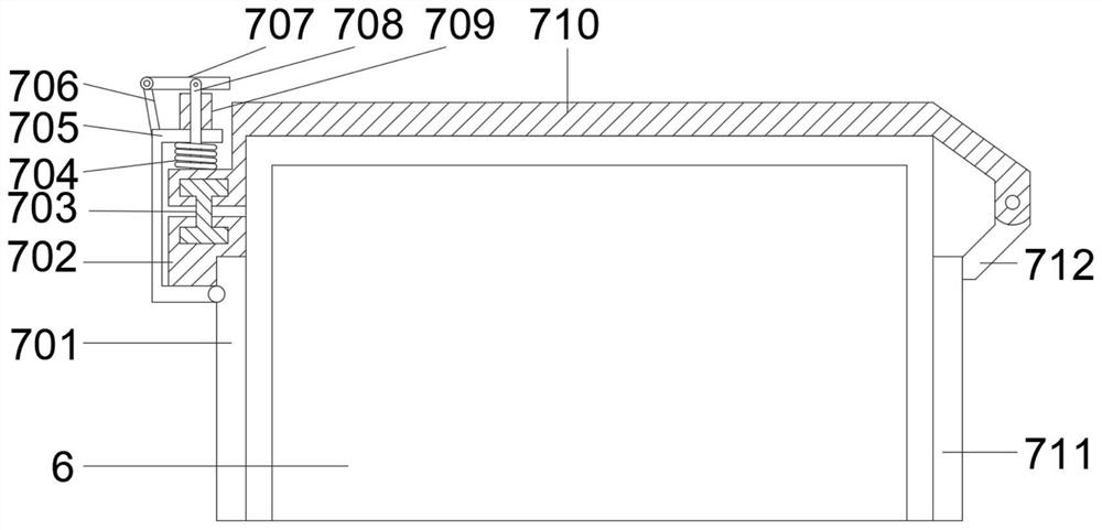
[0076] A casing 1, inside the casing 1 is fixedly installed a battery 6, a converter 5 and a controller, and the upper end of the battery 6 is provided with a battery fixing device 7;

[0077] The upper end of the outer surface of the housing 1 is provided with a lifting device 4, one side of the outer surface of the housing 1 is provided with a heat sink 2 and a socket 3, the outer surface of the housing 1 is also provided with a control panel 10, the converter 5 and The storage battery 6 is electrically connected to the socket 3, and the control panel 10, the converter 5, and the storage battery are all electrically connected to the controller.

[0078] The beneficial effects of the above-mentioned technical solution are: the converter 5 and the storage battery 6 are arranged inside the casing 1 to realize the function of...

Embodiment 2

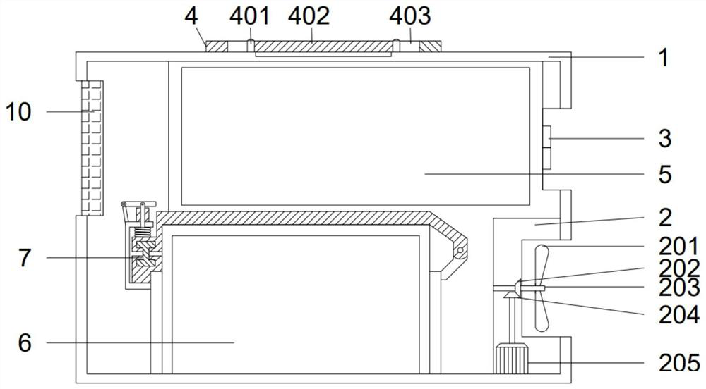
[0080] see figure 2 , on the basis of embodiment 1, the present invention provides a kind of technical scheme:

[0081] A structure of a portable energy storage power station, the heat dissipation device 2 includes:

[0082] Heat dissipation fan blade 201, driven bevel gear 202, rotating shaft 203, driving bevel gear 204, heat dissipation motor 205;

[0083] The heat dissipation motor 205 is fixedly mounted on the inner bottom of the housing 1, the heat dissipation motor 205 is fixedly mounted with a driving bevel gear 204, and the driving bevel gear 204 is meshed with a driven bevel gear 202, and the driven bevel gear 202 is fixed Installed on the rotating shaft 203 , the rotating shaft 203 is rotatably connected with the casing 1 , and the cooling fan blade 201 is fixedly installed on one end of the rotating shaft 203 outside the casing 1 .

[0084] The beneficial effect of the above technical solution is: when the heat dissipation device 2 is working, the heat dissipatio...

Embodiment 3

[0086] see figure 2 , on the basis of embodiment 1, the present invention provides a kind of technical scheme:

[0087] A structure of a portable energy storage power station, the lifting device 4 includes:

[0088] Fixed nail 401, lifting belt 402, chute 403;

[0089] Both ends of the lifting belt 402 are symmetrically provided with chute 403, and the lifting belt 402 in the chute 403 is fixed on the outer upper end of the shell 1 by fixing nails 401;

[0090] A groove is provided at the lower end of the lifting belt 402 at the part of the housing 1 .

[0091] The beneficial effect of the above technical solution is: when using the lifting device 4, the staff can lift the portable energy storage power station through the lifting belt 402, which is convenient for transportation.


PUM


Abstract

The invention discloses a structure of a portable energy storage power station, and the structure comprises a shell, wherein a storage battery, a converter and a controller are fixedly installed in the shell, and a battery fixing device is arranged at the upper end of the storage battery; a lifting device is arranged at the upper end of the outer surface of the shell, a heat dissipation device and a socket are arranged on one side of the outer surface of the shell, a control panel is further arranged on the outer surface of the shell, a converter is electrically connected with a storage battery and the socket, and the control panel, the converter and the storage battery are all electrically connected with a controller. According to the portable energy storage power station, the converter and the storage battery are arranged in the shell, the effect of storing and outputting electric energy is achieved, the work of providing the electric energy is completed, and the heat dissipation device is arranged at one end of the storage battery, so the heat dissipation device can timely transmit heat generated when the storage battery works out, and the work of cooling the portable energy storage power station is completed; through the lifting device at the upper end of the outer surface of the shell, a user can conveniently carry the energy storage power station, and the problem that the energy storage power station is inconvenient to carry is solved.

Description

technical field [0001] The invention relates to an energy storage power station device, in particular to a structure of a portable energy storage power station. Background technique [0002] Nowadays, people are increasingly inseparable from electricity in their daily life. When working in the field or doing outdoor activities, they often need to carry energy storage power stations to provide the power needed for work and life. Portable energy storage power stations are used as power supply equipment for outdoor life and work. increasingly demanded by people; [0003] The current portable energy storage power station has technical deficiencies such as prolonged use that will lead to higher and higher internal temperatures of the energy storage power station, inability to cool down in time, and inconvenient handling; [0004] Aiming at the deficiencies of the existing technology, the present invention provides a structure of a portable energy storage power station. Content...

Claims


Application Information

Patent Timeline
Patent Type & Authority Applications(China)
IPC IPC(8): H01M50/244H01M50/258H01M50/251H01M10/613H01M10/635H01M10/6551H01M10/6563H05K7/20H01M10/48
CPCH05K7/20172H01M10/613H01M10/635H01M10/6551H01M10/6563H01M10/486Y02E60/10
Inventor 罗磊朱祥明冯少君
Owner 深圳市恒泰能源科技有限公司
Why Eureka
Try Eureka