The structure of portable energy storage power station
An energy storage power station, portable technology, applied in the direction of structural parts, electrical equipment construction parts, circuits, etc., can solve the problems of inconvenient handling, the inability of portable energy storage power stations to be cooled in time, etc., to improve stability and service life , The internal stability of the structure, the effect of preventing movement
- Summary
- Abstract
- Description
- Claims
- Application Information
AI Technical Summary
Problems solved by technology
Method used
Image
Examples
Embodiment 1
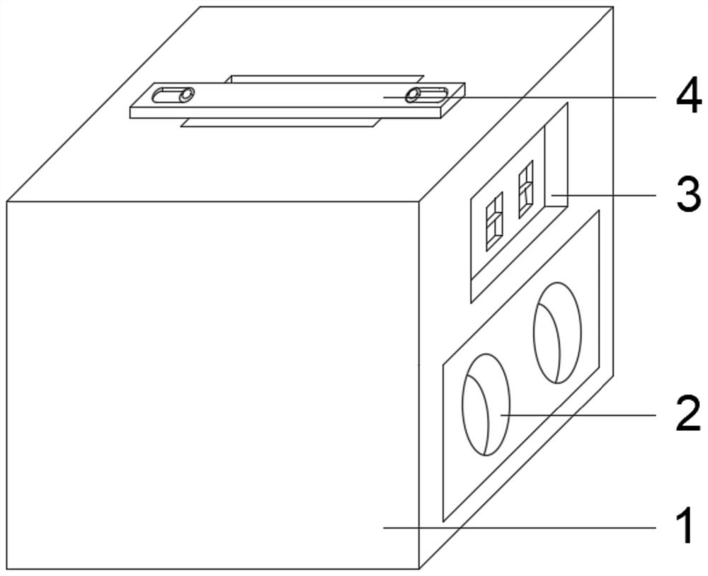
[0074] see figure 1 , the present invention provides a technical solution:
[0075] A structure of a portable energy storage power station, comprising:
[0076] A casing 1, inside the casing 1 is fixedly installed a battery 6, a converter 5 and a controller, and the upper end of the battery 6 is provided with a battery fixing device 7;
[0077] The upper end of the outer surface of the housing 1 is provided with a lifting device 4, one side of the outer surface of the housing 1 is provided with a heat sink 2 and a socket 3, the outer surface of the housing 1 is also provided with a control panel 10, the converter 5 and The storage battery 6 is electrically connected to the socket 3, and the control panel 10, the converter 5, and the storage battery are all electrically connected to the controller.
[0078] The beneficial effects of the above-mentioned technical solution are: the converter 5 and the storage battery 6 are arranged inside the casing 1 to realize the function of...
Embodiment 2
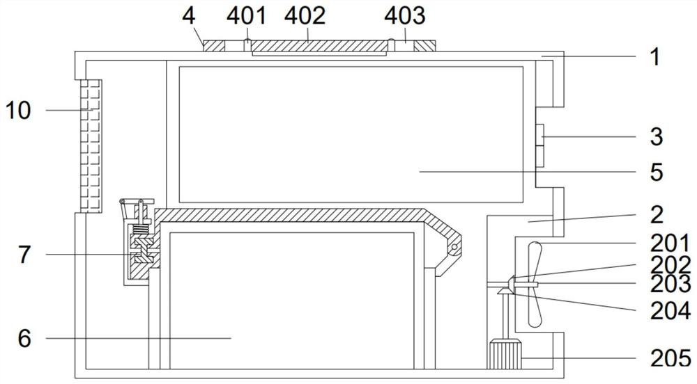
[0080] see figure 2 , on the basis of embodiment 1, the present invention provides a kind of technical scheme:
[0081] A structure of a portable energy storage power station, the heat dissipation device 2 includes:
[0082] Heat dissipation fan blade 201, driven bevel gear 202, rotating shaft 203, driving bevel gear 204, heat dissipation motor 205;
[0083] The heat dissipation motor 205 is fixedly mounted on the inner bottom of the housing 1, the heat dissipation motor 205 is fixedly mounted with a driving bevel gear 204, and the driving bevel gear 204 is meshed with a driven bevel gear 202, and the driven bevel gear 202 is fixed Installed on the rotating shaft 203 , the rotating shaft 203 is rotatably connected with the casing 1 , and the cooling fan blade 201 is fixedly installed on one end of the rotating shaft 203 outside the casing 1 .
[0084] The beneficial effect of the above technical solution is: when the heat dissipation device 2 is working, the heat dissipatio...
Embodiment 3
[0086] see figure 2 , on the basis of embodiment 1, the present invention provides a kind of technical scheme:
[0087] A structure of a portable energy storage power station, the lifting device 4 includes:
[0088] Fixing nail 401, lifting belt 402, chute 403;
[0089] Both ends of the lifting belt 402 are symmetrically provided with chute 403, and the lifting belt 402 in the chute 403 is fixed on the outer upper end of the shell 1 by fixing nails 401;
[0090] A groove is provided at the lower end of the lifting belt 402 at the part of the housing 1 .
[0091] The beneficial effect of the above technical solution is: when using the lifting device 4, the staff can lift the portable energy storage power station through the lifting belt 402, which is convenient for transportation.
PUM
 Abstract
Description
Claims
Application Information
 - R&D
- Intellectual Property
- Life Sciences
- Materials
- Tech Scout
- Unparalleled Data Quality
- Higher Quality Content
- 60% Fewer Hallucinations
Browse by: Latest US Patents, China's latest patents, Technical Efficacy Thesaurus, Application Domain, Technology Topic, Popular Technical Reports.
© 2025 PatSnap. All rights reserved.Legal|Privacy policy|Modern Slavery Act Transparency Statement|Sitemap|About US| Contact US: help@patsnap.com


