
Oil well cementing cement degassing device

A technology of oil well cementing and cement, which is applied in the field of oil well cementing, can solve the problems of reducing the use effect and service life, and achieve better results

Inactive Publication Date: 2018-08-14
CHINA UNIV OF GEOSCIENCES (BEIJING)
View PDF9 Cites 0 Cited by
  • Summary
  • Abstract
  • Description
  • Claims
  • Application Information

AI Technical Summary

Problems solved by technology

[0002] Bubbles will inevitably appear in the cement used in the cementing process of oil wells in the process of mixing with water. If these bubbles cannot be effectively discharged or reduced, it will have a great impact on the entire cementing well wall, not only reduce the Its use effect will also reduce its service life. Most of the solutions today are to add some chemical substances such as degassing additives to degas or reduce air bubbles. This method has certain limitations. The additive itself needs to be stirred evenly. It will play a role, and it will also be affected by factors such as failure and onset time, and may not work in time

Method used


Image

  • Oil well cementing cement degassing device
  • Oil well cementing cement degassing device
  • Oil well cementing cement degassing device

Examples


Embodiment Construction

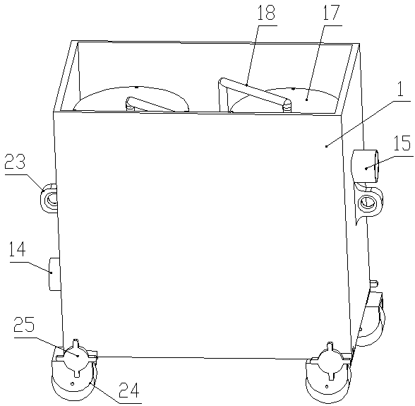
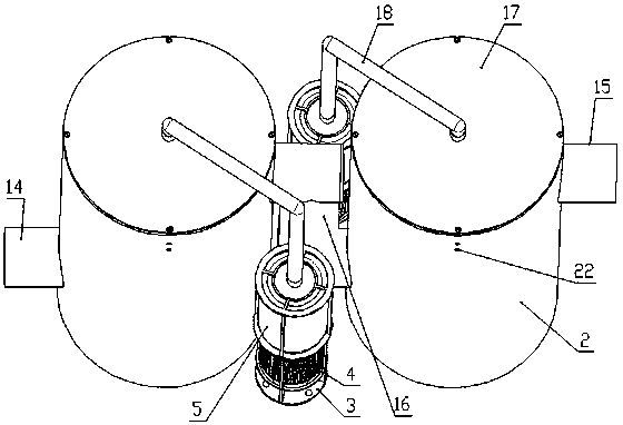
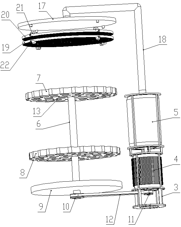
[0021] Such as figure 1 , figure 2 and image 3 As shown, the air-removing device for oil well cementing cement of the present invention includes a rectangular parallelepiped-shaped shell 1, and two sets of stirring and pumping systems are arranged in the shell 1.

[0022] Each set of agitating and pumping system includes a mixing bucket 2, an installation frame 3, a motor 4, a vacuum pump 5, a stirring shaft 6, an upper stirring plate 7 and a lower stirring plate 8. 2. The lower part of the inner part is horizontally provided with a base plate 9. The lower edge of the mixing tank 2 and the lower end of the installation frame 3 are fixed on the upper surface of the bottom of the shell 1. There is a gap between the base plate 9 and the bottom of the shell 1. The motor 4 and the vacuum pump 5 are located in the installation On the frame 3, the motor 4 is located below the vacuum pump 5, and the stirring shaft 6 is arranged in the mixing tank 2 along the center line. Driving ...


PUM


Abstract

An oil well cement bubble removing device comprises a shell. Two stirring and air exhausting systems are arranged in the shell. Each stirring and air exhausting system comprises a stirring tank, an installation frame, a motor, a vacuum pump, a stirring shaft, an upper stirring disk and a lower stirring disk. The motors and the vacuum pumps are arranged on the installation frames. The lower portion of one side of each stirring tank is provided with a cement inlet pipe connector, and the upper portion of the other side of each stirring tank is provided with a cement outlet pipe connector. The cement inlet pipe connector of one stirring and air exhausting system and the cement outlet pipe connector of the other stirring and air exhausting system both penetrate the side portions of the shell and extend out, and the other cement inlet pipe and the other cement outlet pipe are connected through a middle connecting pipe. The top of each stirring tank is provided with a tank cover. The top of each tank cover is provided with an air exhausting hole. The vacuum pumps are connected with the air exhausting hole through an air exhausting pipe. The oil well cement bubble removing device is simple in overall structure, the oil well cement bubble removing device is additionally arranged on the premise of not changing the original pipeline design, and the oil well cement bubble removing device is reliable in principle and capable of greatly lowering the bubble content in cement and achieves better effect after cement solidification.

Description

technical field [0001] The invention belongs to the technical field of oil well cementing, in particular to an oil well cementing cement air-removing device. Background technique [0002] Bubbles will inevitably appear in the cement used in the cementing process of oil wells in the process of mixing with water. If these bubbles cannot be effectively discharged or reduced, it will have a great impact on the entire cementing well wall, not only reduce the Its use effect will also reduce its service life. Most of the solutions today are to add some chemical substances such as degassing additives to degas or reduce air bubbles. This method has certain limitations. The additive itself needs to be stirred evenly. It will play a role, and it will also be affected by factors such as failure and onset time, and may not necessarily work in time. Contents of the invention [0003] In order to solve the deficiencies in the prior art, the present invention provides an oil well cementi...

Claims


Application Information

Patent Timeline
Patent Type & Authority Patents(China)
IPC IPC(8): B28C5/16B28C5/46
CPCB28C5/0806B28C5/0831B28C5/166B28C5/464
Inventor 陶树李松张国伟
Owner CHINA UNIV OF GEOSCIENCES (BEIJING)
Learn More