
Device for foaming a liquid

a liquid foaming and liquid technology, applied in the direction of mixers, heating types, fuel gas production, etc., can solve the problems of difficult to remove contaminants, deposited contaminants on the inside of the pipe, etc., and achieve the effect of convenient cleaning, simple design and effective foaming

Active Publication Date: 2005-11-24
MELITTA EUROPA
View PDF11 Cites 39 Cited by
  • Summary
  • Abstract
  • Description
  • Claims
  • Application Information

AI Technical Summary

Benefits of technology

[0005] It is an object of the present invention to create a device for foaming a liquid which has a simple design, permits an effective foaming, and is easy to clean.
[0007] Thus, according to the invention, a steam-air mixture is fed via a pipe into the region of the agitator and is then whirled together with the liquid. As a result, the agitator can be adapted optimally to the foaming requirements and, in particular, can ensure a sufficient stirring up of the liquid. The arrangement can furthermore be operated hygienically since only the steam-air mixture is supplied via the pipe, and the liquid to be foamed for the most part cannot deposit contaminants in this region. Further, at least the regions coming into contact with the liquid to be foamed are easily accessible for the purpose of cleaning.
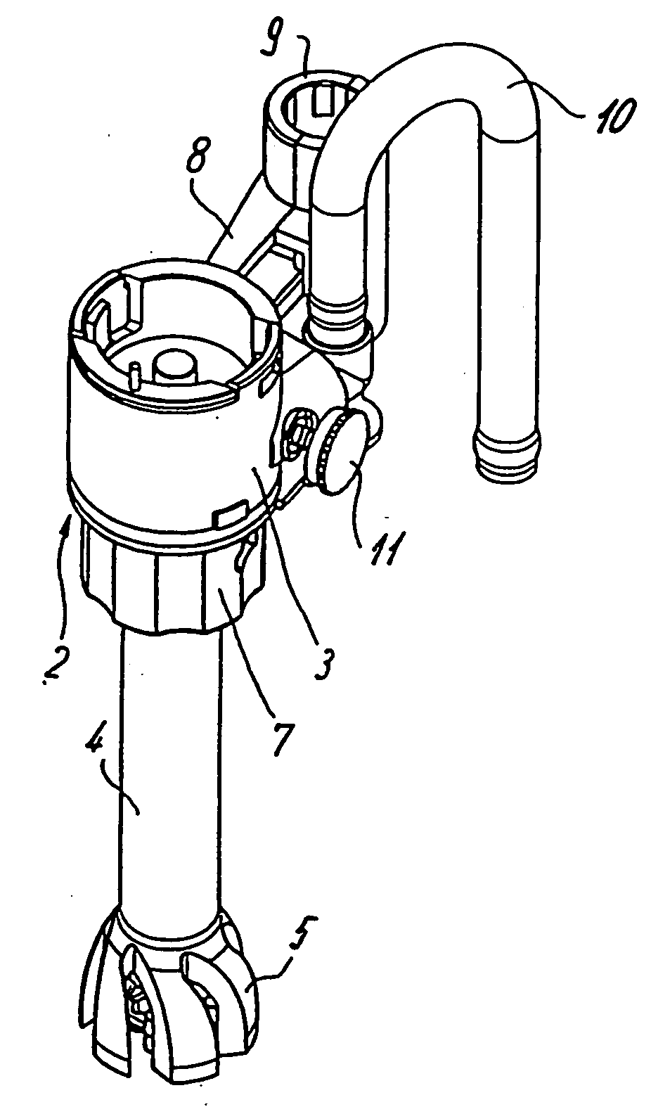
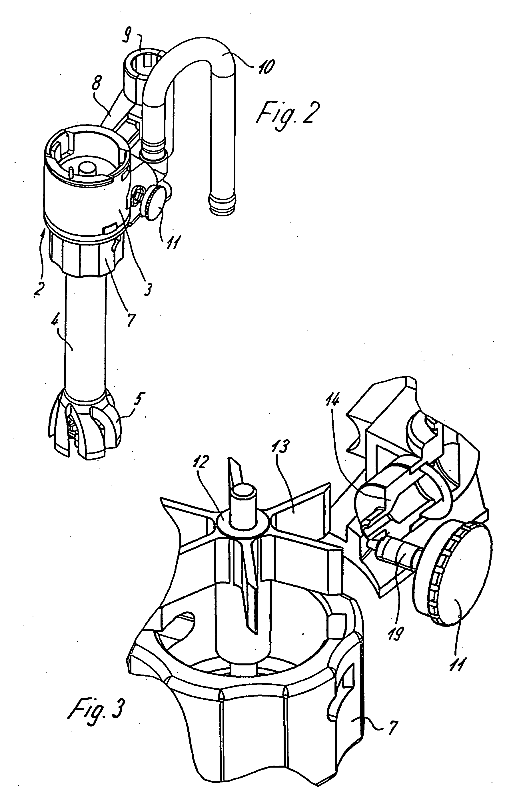
[0008] According to one preferred embodiment of the invention, a ring-shaped cover containing several flow-through openings is provided in the area surrounding the agitator. On the one hand, this cover functions to calm down the flow that is whirled up by the agitator while, on the other hand, the cover protects the agitator against damage when it is submerged into a container. The cover is preferably provided with several webs which form flow surfaces that are inclined relative to a radial direction of the rotational axis for the agitator. As a result, the flow can be calmed particularly well, wherein these webs have the additional advantage of being easy to clean and having an open structure.
[0009] It is preferable if the agitator together with the shaft can be removed from a section of the turbine casing for the purpose of cleaning wherein the individual components can be dismantled further to realize a thorough cleaning at specific intervals. The ability to remove the agitator has the advantage that for the most part the agitator is submerged pointing downward into a container. By pulling off the agitator, it is easily accessible from below and can be cleaned with a brush together with the cover.
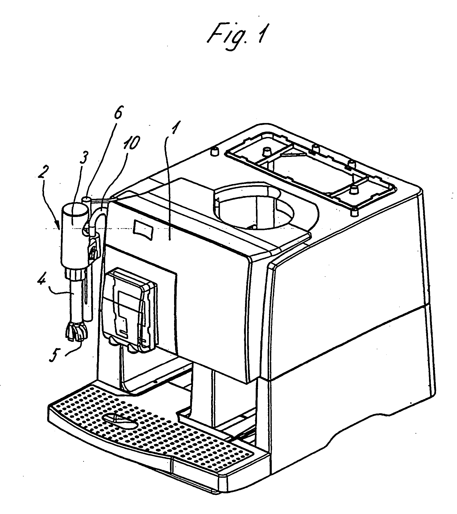
[0010] For an easy handling of the device, the unit consisting of casing, turbine, agitator, and pipe can be moved vertically up and down, wherein other components can also be displaced along with this unit. These components are not explicitly mentioned herein and may include, for example, a connection for the steam feed-in, valves, seals, and the like. This unit is preferably positioned pivoting on a holder, so that the agitator can be submerged for use into a container and can subsequently be removed again in upward direction and pivoted to the side to permit the removal of the container.
[0012] According to a another embodiment of the invention, the amount of air which can be added is adjustable, wherein the type of foam obtained can be varied by changing the amount of air. For example, foam that is more delicate but lasts longer is generated when a lower amount of air is supplied, wherein the air can be suctioned in using a venturi effect.

Problems solved by technology

The disadvantage of this device is that the liquid to be foamed is in direct contact with the turbine wheel, thus making it possible for contaminants to be deposited which are the difficult to remove.
In addition, the turbine wheel is designed to simultaneously function as an agitator, which is a disadvantage since the turbine rotation is not optimally directed toward the generating of foam.
As a result, contaminants that are hard to remove can be deposited on the inside of the pipe.

Method used


Image

  • Device for foaming a liquid
  • Device for foaming a liquid
  • Device for foaming a liquid

Examples


Embodiment Construction

[0021] Referring to FIG. 1, there is shown an automatic coffee maker 1 with a box-shaped design which includes a device, known per se, for grinding beans and brewing coffee. A device 2 for foaming a liquid, in particular milk, is arranged to one side of the automatic coffee maker 1. The device 2 comprises a casing 3, provided with a pipe 4 on the underside, wherein a bell-shaped, expanding cover 5 is formed onto the pipe end. The casing 3 is positioned by means of a holder and a rod 6 on the automatic coffee maker 1, such that the device can be displaced in height and can be pivoted.

[0022]FIG. 2 shows that a lower region of casing 3 contains a casing ring 7 which can be attached to and / or detached from the casing 3 by a bayonet fastener. An extension arm 8 is formed onto the casing 3 and is provided with a sleeve 9 on its end, wherein sleeve 9 is guided along the rod 6. In the process, the sleeve 9 can be locked in place for different rotational positions along the rod 6 to ensure ...


PUM

PropertyMeasurementUnit
areaaaaaaaaaaa
heightaaaaaaaaaa
flexibleaaaaaaaaaa

Abstract

A device for foaming a liquid includes a casing with a turbine arranged inside the casing. A shaft connects an agitator with the turbine. An air supply nozzle is coupled to the casing and a tube is coupled to the casing for conducting a steam supply to drive the turbine. A pipe is connected between the agitator and the turbine to introduce a steam-air mixture to a region of the agitator. The steam-air mixture is whirled together with the liquid when the agitator is immersed in the liquid.

Description

CROSS-REFERENCE TO RELATED APPLICATION [0001] This application claims the priority of German Patent Application No. 10 2004 024 721.8, filed on May 19, 2004, the subject matter of which is incorporated herein by reference. The disclosure of all U.S. patents and patent applications mentioned below are also incorporated herein by reference. BACKGROUND OF THE INVENTION [0002] The present invention relates to a device for foaming a liquid, in particular milk, the device comprising a steam supply unit for operating a turbine positioned inside a casing, as well as a device for supplying air, wherein the turbine is connected by a shaft to an agitator for whirling the liquid. [0003] International Patent Application Publication No. WO 90 / 10411 discloses a device for foaming and simultaneously heating a liquid such as milk, wherein a turbine wheel driven by hot steam functions to suction the liquid to be foamed into an emulsifying cage where the liquid is whirled. The disadvantage of this dev...

Claims


Application Information

Patent Timeline
Patent Type & Authority Applications(United States)
IPC IPC(8): A47J31/44A47J43/12
CPCA47J31/4489Y10S261/26A47J43/127
Inventor ROHDE, FLORIAN
Owner MELITTA EUROPA
Learn More