Image display device and head-mounted display comprising same

A technology for image display and display components, applied in instruments, optics, magnifying glasses, etc., can solve the problems of large display components, sacrificing system compactness, and high cost

Inactive Publication Date: 2003-12-24
KONINKLIJKE PHILIPS ELECTRONICS NV
View PDF1 Cites 1 Cited by
  • Summary
  • Abstract
  • Description
  • Claims
  • Application Information

AI Technical Summary

Problems solved by technology

[0005] A disadvantage of the described image display device is that, if the desired highest resolution is to be achieved, the display elements must be rather large and consequently expensive
Another disadvantage is that when the display element is a reflective display panel, optical coupling is hindered because the forward and projected beams travel along the same optical path
One solution to this problem is to use dichroic prisms or dichroic mirrors, but this comes at the expense of system compactness with a relatively large display element

Method used


Image

  • Image display device and head-mounted display comprising same
  • Image display device and head-mounted display comprising same
  • Image display device and head-mounted display comprising same

Examples


Embodiment Construction

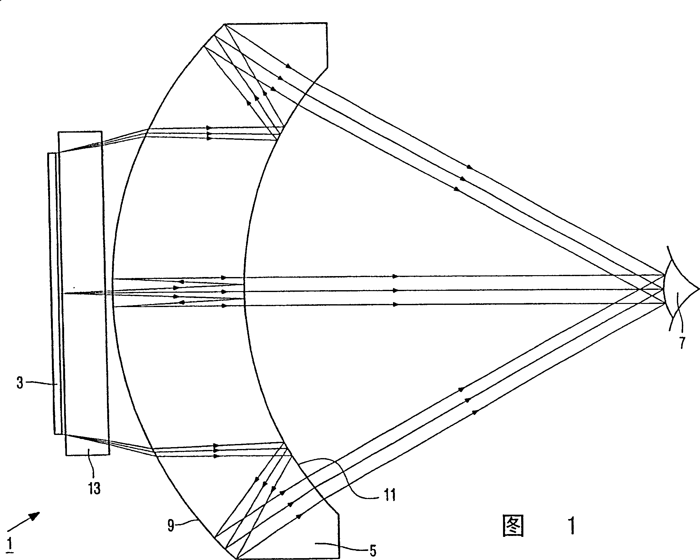
[0034] The image display device 1 shown schematically in FIG. 1 comprises a display element 3 and an optical system consisting of a lens system in the form of a single mirror lens 5 . The image generated by the display element 3 is projected through the optical system into the pupil of the eye 7 of the observer. The mirror lens 5 has a first semitransparent surface 9 and a second semitransparent surface 11 . Light is preferably transmitted at least once and reflected at least once by the first and second transflective surfaces. Figure 1 shows the radiation paths of three pixels. The first semi-transparent surface 9 and the second semi-transparent surface 11 are preferably adapted in such a way that the radiation beam transmitted through the first semi-transparent surface 9 in the direction towards the observer is transmitted by the second semi-transparent surface 11. The radiation beam reflected by the second face 11 is then reflected by the first half-transparent face 9 . ...


PUM


Abstract

The present invention relates to an image display device (1) comprising a two-dimensional display (3; 19, 21; 72) and an optical system (5; 15, 17; 60). The optical system comprises a lens having a first semitransparent reflecting surface (23, 25; 9) and a second semitransparent reflecting surface (27, 29; 11). The first surface is directed towards the display. The second surface is directed towards the viewer. Both the display and the lens are divided into a plurality of segments in order to increase the field of view.

Description

technical field [0001] The invention relates to an image display device comprising at least one two-dimensional display element and an optical system comprising a lens system having a first semi-transparent surface and a second semi-transparent surface, the first semi-transparent surface pair facing the display element, the second transflective surface is away from the display element. [0002] The invention also relates to a head-mounted display comprising such an image display device. Background technique [0003] An image display device of the type described in the opening paragraph is known, for example, from US-A 5,659,430. The image display device described in this patent includes a two-dimensional display element and an optical system through which an image generated by the display element is imaged to the eyes of a viewer. The optical system consists of an embedded mirror lens. Such a lens has first and second transflective surfaces through which incident light ra...

Claims


Application Information

Patent Timeline
IPC IPC(8): G02B17/08G02B17/00G02B25/00G02B27/00G02B27/01G02B27/02
CPCG02B2027/0132G02B27/0172G02B2027/011G02B2027/0178G02B27/02
Inventor W·奥菲
Owner KONINKLIJKE PHILIPS ELECTRONICS NV
Why Eureka
Try Eureka