Spatial position adjusting device

A technology of spatial position and adjustment device, applied in shaft installation, bearing assembly, bearing and other directions, can solve problems such as inability to meet precise fit and poor adjustment flexibility.

Active Publication Date: 2021-09-10
ANHUI UNIVERSITY OF TECHNOLOGY AND SCIENCE
View PDF15 Cites 1 Cited by
  • Summary
  • Abstract
  • Description
  • Claims
  • Application Information

AI Technical Summary

Problems solved by technology

The existing space position adjustment device cannot meet the precise cooperation between the various components, and the adjustment flexibility is poor. Therefore, we propose a space position adjustment device

Method used


Image

  • Spatial position adjusting device
  • Spatial position adjusting device
  • Spatial position adjusting device

Examples


Embodiment 1

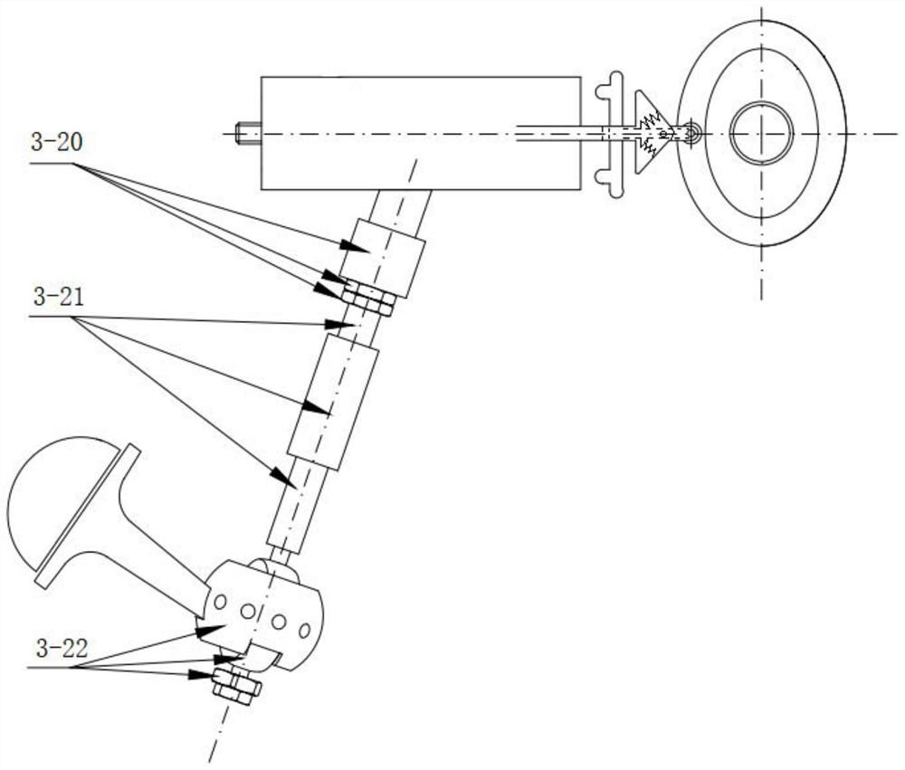
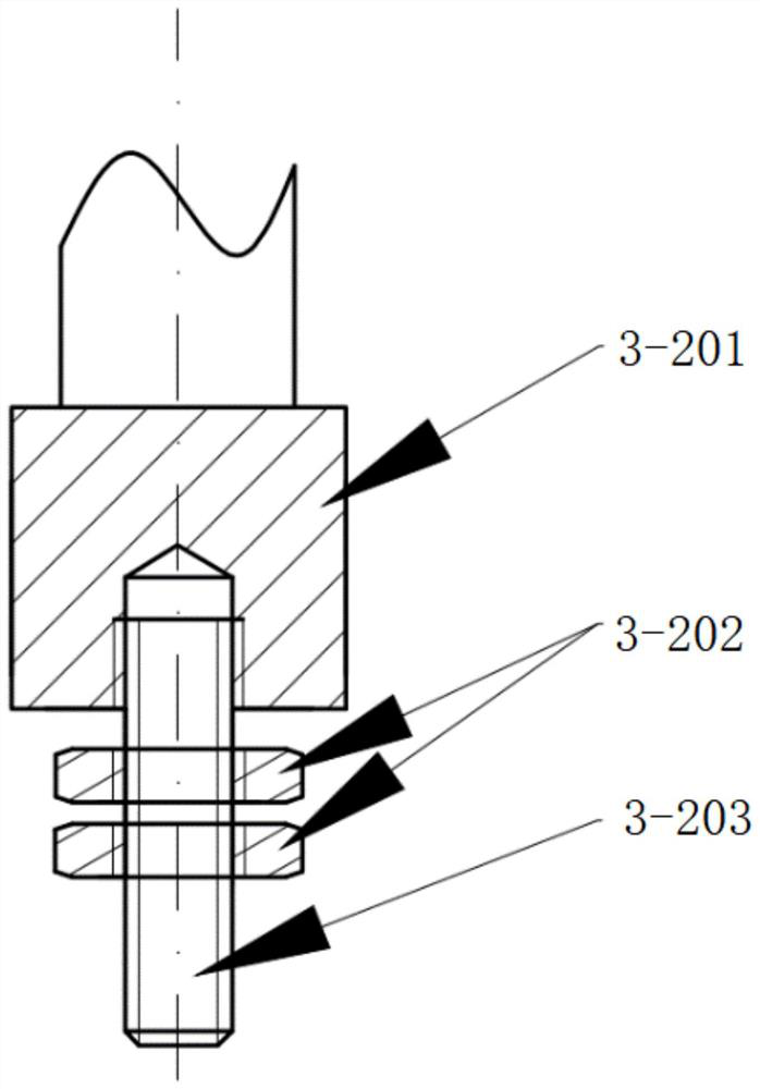
[0025] see Figure 1-5 , an embodiment provided by the present invention: a spatial position adjustment device for adjusting and fixing the spatial position of the member to be adjusted, which has a fixed seat 3-20, a telescopic rod 3-21 and a universal ball 3-22, Wherein, the universal ball 3-22 includes an outer drum shell 3-223 and a drum-shaped inner drum, the inner wall of the outer drum shell 3-223 is equal in diameter to the inner drum, and the outer drum The spherical shell 3-223 is in rolling contact with the inner drum, and the inner wall surface of the outer drum shell 3-223 and the outer wall surface of the inner drum have a certain roughness. When the inner drum is placed on the screw C 3-213 , the outer drum shell 3-223 is fixed by the fixed arm, and the fixed arm can be set on the fixed part. When adjusting the spatial position of the two parts, the screw rod C 3-213 drives the inner drum ball, which can not only surround the outer drum shell The 3-223 centerli...

Embodiment 2

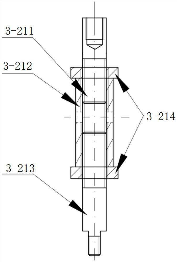
[0028] When this kind of space position adjustment device is used for position adjustment between two parts, such as when the car is running, the space position between the two parts needs to be flexibly matched. 3-224 and half drum 3-225 are tightened and connected together to form an inner drum, and the connected inner drum enters the inside of the outer drum shell 3-223 through the half groove of the outer drum shell 3-223, and the inner drum Drum ball and outer drum shell 3-223 rolling contact, such as Figure 4 As shown, the telescopic rod 3-21 placed on the inner drum can not only be rotated 360°, but also can be rotated arbitrarily within the angle range of the space cone not greater than 90° according to the required angle. At the same time, the rotation The sleeve nut 3-212 can make the screw rod B 3-212 and the screw rod C 3-213 protrude or retract at the same time, and through the cooperation with the universal ball 3-22, the flexibility of the spatial position betw...


PUM


Abstract

The invention relates to the technical field of part position adjustment, and discloses a spatial position adjusting device which is used for spatial position adjustment and fixing of a part to be adjusted and provided with a fixing base, a telescopic rod and a universal ball, wherein the universal ball comprises an outer drum ball shell and an inner drum ball with the drum-shaped appearance; the inner drum ball is composed of a half drum ball A, a half drum ball B, a fastening screw rod and a locking nut, wherein a threaded through hole penetrating through the center of the inner drum ball is formed in the spherical surface directly facing the inner drum ball, and the portions, in the half drum ball A and the half drum ball B, of the threaded through hole are exactly provided with opposite threaded structures, so that the fastening screw rod screwed in the threaded through hole can enable the half drum ball A and the half drum ball B to be pushed away, expanded or contracted and tensioned; the fastening screw rod is locked and fixed through the locking nut; and an external thread corresponding to the threaded through hole in the half drum ball A is formed at the lower end of the screw rod C. The spatial position adjusting device can accurately and flexibly regulate the spatial position as required, is convenient to operate, and easy to disassemble and maintain.

Description

technical field [0001] The invention relates to component position adjustment technology, in particular to a space position adjustment device. Background technique [0002] With the development of industry, various industries have entered into a state of mechanization. During the assembly process of mechanisms composed of multiple components and the production process of workpieces to be processed, it is often necessary to adjust the relative position of each component to facilitate the assembly of the staff, especially for the spatial position. More accurate parts are required. The existing space position adjustment device cannot meet the precise cooperation between various components, and the adjustment flexibility is poor. Therefore, we propose a space position adjustment device. To this end, we propose a spatial position adjustment device. Contents of the invention [0003] 1. Technical problems to be solved [0004] The technical problem to be solved by the present...

Claims


Application Information

Patent Timeline
Patent Type & Authority Applications(China)
IPC IPC(8): F16C11/06F16C7/06
CPCF16C11/0609F16C11/0614F16C11/0695F16C7/06F16C2326/01F16C2226/60
Inventor 高清振高菲张荣芸曹赟博张祖安许毅
Owner ANHUI UNIVERSITY OF TECHNOLOGY AND SCIENCE
Why Eureka
Try Eureka