Waste gas treatment device for powder spraying production line

A technology for waste gas treatment device and production line, which is applied in gas treatment, dispersed particle filtration, membrane technology, etc., and can solve the problems of inconvenient replacement or cleaning of parts, poor filtration effect, and incomplete filtration.

Pending Publication Date: 2021-10-15
青岛海尔能源动力有限公司
View PDF6 Cites 0 Cited by
  • Summary
  • Abstract
  • Description
  • Claims
  • Application Information

AI Technical Summary

Problems solved by technology

[0003] However, in the process of using the traditional exhaust gas treatment device, there are shortcomings such as incomplete filtration and poor filtering effect, and there are problems that the filtering parts are inconvenient to replace or clean.

Method used


Image

  • Waste gas treatment device for powder spraying production line
  • Waste gas treatment device for powder spraying production line
  • Waste gas treatment device for powder spraying production line

Examples


no. 1 example

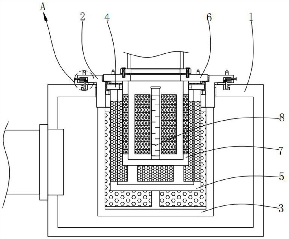
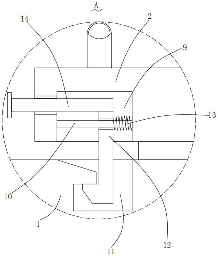
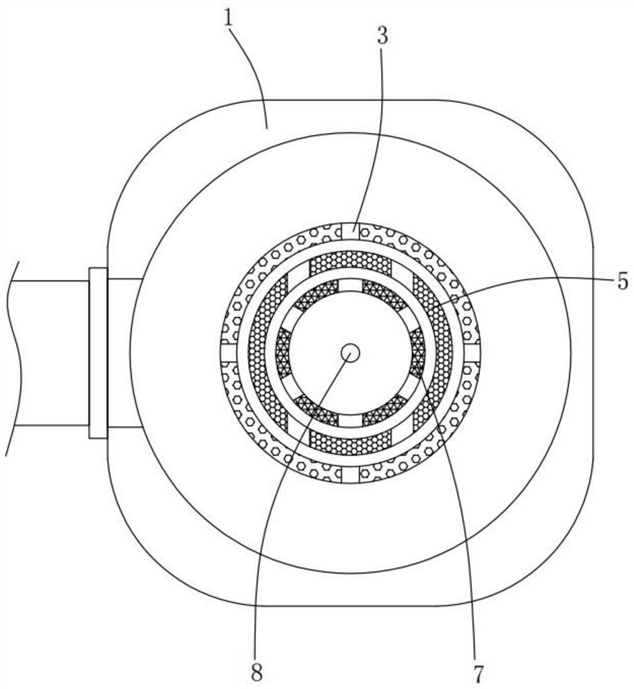
[0024] Please refer to Figure 1-3 , in the first embodiment of the present invention, the exhaust gas treatment device for the powder spraying production line includes: a housing 1; The bottom end of the bottom extends into the housing 1; the first filter barrel 3, the first filter barrel 3 is fixedly installed on the bottom of the screw 2; the first threaded ring 4, the first threaded ring 4 is installed in a sealed thread In the threaded member 2; the second filter barrel 5, the second filter barrel 5 is fixedly installed on the bottom of the first threaded ring 4; the second threaded ring 6, the second threaded ring 6 is installed in a sealed thread In the threaded part 2; the third filter bucket 7, the third filter bucket 7 is fixedly installed on the bottom of the second threaded ring 6; the high-strength ultraviolet lamp tube 8, the high-strength ultraviolet lamp tube 8 is fixedly installed on the The third filter barrel 7.

[0025] The threaded part 2 is symmetricall...

no. 2 example

[0035] Based on the waste gas treatment device for a powder spraying production line provided in the first embodiment of the present application, the second embodiment of the present application proposes another waste gas treatment device for a powder spraying production line. The second embodiment is only a preferred mode of the first embodiment, and the implementation of the second embodiment will not affect the independent implementation of the first embodiment.

[0036] The second embodiment of the present invention will be further described below in conjunction with the drawings and implementation methods.

[0037] Please refer to Figure 4 , the exhaust gas treatment device for the powder spraying production line also includes an installation shell 15, the installation shell 15 is fixedly installed on the bottom of the housing 1, and the bottom of the first filter barrel 3 is rotatably installed with a rotating column 16, and the rotating column Two push rods 17 are sym...


PUM


Abstract

The invention provides a waste gas treatment device for a powder spraying production line. The waste gas treatment device for the powder spraying production line comprises a shell, a threaded part, a first filtering barrel, a first threaded ring, a second filtering barrel, a second threaded ring and a third filtering barrel; the threaded part is movably mounted on the shell in a sealed mode, and the bottom end of the threaded part extends into the shell; the first filtering barrel is fixedly mounted at the bottom of the threaded part; the first threaded ring is mounted in the threaded part in a sealing and threaded manner; the second filtering barrel is fixedly mounted at the bottom of the first threaded ring; the second threaded ring is mounted in the threaded part in a sealing and threaded manner; and the third filtering barrel is fixedly mounted at the bottom of the second threaded ring. The waste gas treatment device for the powder spraying production line, provided by the invention, has the advantages of convenience in use, simplicity in operation, more thorough filtration, good filtration effect and convenience in replacement or cleaning of parts for filtration.

Description

technical field [0001] The invention relates to the technical field of waste gas treatment, in particular to a waste gas treatment device for a powder spraying production line. Background technique [0002] Powder spraying refers to a coating process that uses corona discharge to make powder coatings adhere to workpieces. After powder spraying, after steps such as hot melting and solidification, a coating film will be formed on the surface of the workpiece. During the powder spraying process, the waste gas generated needs to be treated to prevent the health of the staff from being affected. In the prior art, the waste gas treatment device to process. [0003] However, during the use of the traditional waste gas treatment device, there are disadvantages such as incomplete filtration and poor filtering effect, and there is a problem that the filtering parts are inconvenient to replace or clean. [0004] Therefore, it is necessary to provide a waste gas treatment device for a...

Claims


Application Information

Patent Timeline
IPC IPC(8): B01D46/00B01D46/24B01D53/00B01D53/04
CPCB01D46/2411B01D53/04B01D53/007B01D2253/102B01D2259/804
Inventor 程登明柴纪强朱亮
Owner 青岛海尔能源动力有限公司
Why Eureka
Try Eureka