Anti-theft device for valve

An anti-theft device and valve technology, applied in valve devices, devices to prevent accidental or unauthorized actions, valve details, etc., can solve the problems of increased workload, poor anti-theft effect, and increased number of patrol inspections. Great flexibility, avoid random operation, enhance the effect of anti-theft performance

Inactive Publication Date: 2022-03-08
范瑶飞
View PDF0 Cites 0 Cited by
  • Summary
  • Abstract
  • Description
  • Claims
  • Application Information

AI Technical Summary

Problems solved by technology

In order to prevent someone from stealing oil by opening the oil discharge valve of the oil storage tank without permission, the workers on duty need to increase the number of patrol inspections, which increases the workload of the workers on duty, and the anti-theft effect is poor

Method used


Image

  • Anti-theft device for valve
  • Anti-theft device for valve
  • Anti-theft device for valve

Examples


Embodiment 1

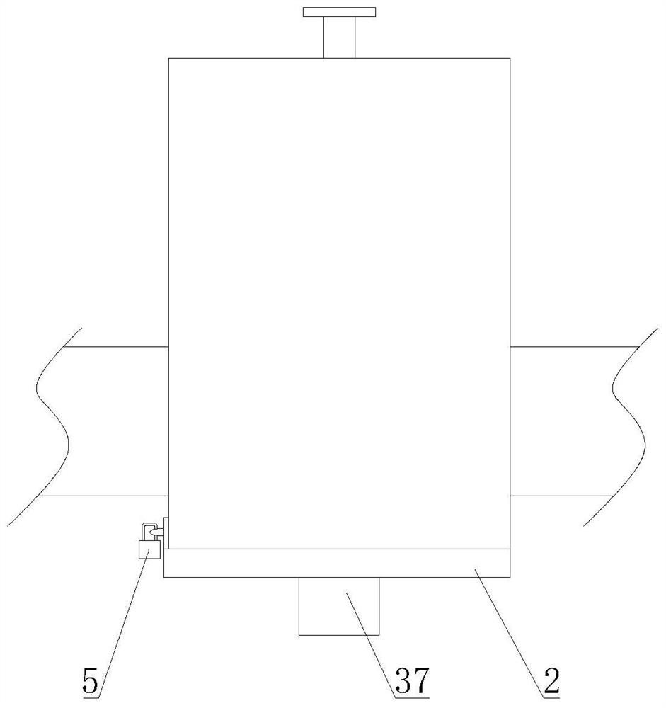
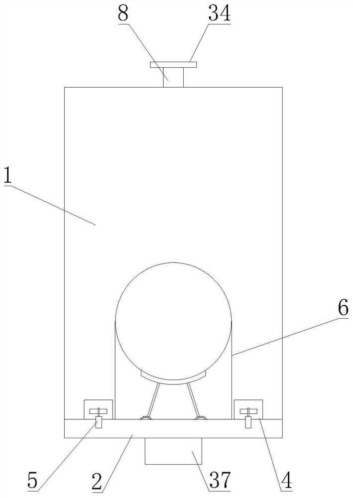
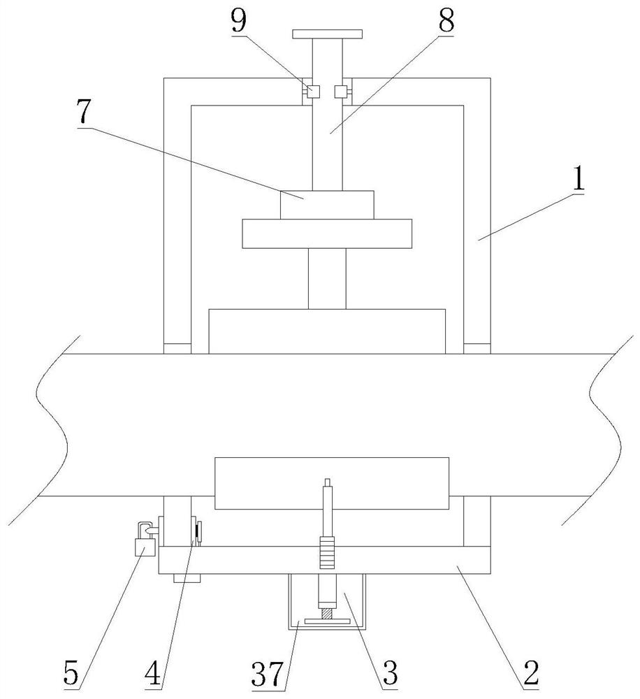
[0039] Such as Figure 1-8 As shown, a valve anti-theft device proposed by the present invention includes an anti-theft box 1, a case cover 2 and a first anti-theft lock 5; the anti-theft box 1 is provided with a U-shaped card slot 6 with the opening facing downward; the box cover 2 is arranged on the U-shaped On the opening end of the type card slot 6, and one end is hinged to the anti-theft box 1, and the other end is connected with the anti-theft box 1 through the first anti-theft lock 5; it also includes a limit assembly 3 and a connection assembly 4; both the limit assembly 3 and the connection assembly 4 are provided On the box cover 2, and cooperate with the pipeline and the first anti-theft lock 5 respectively; the limit assembly 3 includes a limit frame 17, a support rod 18, a first gear 19, a moving frame 20, a rack 35, a threaded rod 21 and a rotating Part 22; threaded rod 21 is rotated and arranged on the bottom of case cover 2; rotating part 22 is arranged on the ...

Embodiment 2

[0050] The present invention also proposes a valve anti-theft method, the steps are as follows:

[0051] S1, open the anti-theft box 1, and clamp the pipe on the U-shaped card slot 6;

[0052] S2. Turn over the box cover 2, pass the adjustment rod 25 of the adjustment assembly 16 through the guide groove 15, make it snap into the first adjustment hole on the limit plate 13, pull the block 12, make it push the outer through hole, and then the outer The connecting plate 10 and the inner connecting plate 11 respectively clamp the two ends of the side wall of the anti-theft box 1, remove the adjustment assembly 16, and the clamping block 12 passes through the through groove and the outer connecting plate 10;

[0053] S3, lock the first anti-theft lock 5;

[0054] S4, open the anti-theft cover 37, rotate the rotating member 22, so that the moving frame 20 rises along the threaded rod 21, the rack 35 drives the first gear 19 to rotate, the support rod 18 pushes the limit frame 17 a...


PUM


Abstract

A valve anti-theft device relates to the field of valves and comprises an anti-theft box, a box cover and a first anti-theft lock. A U-shaped clamping groove with a downward opening is formed in the anti-theft box; the box cover is arranged at the opening end of the U-shaped clamping groove, one end is hinged to the anti-theft box, and the other end is connected with the anti-theft box through a first anti-theft lock; the device further comprises a limiting assembly and a connecting assembly. The limiting assembly and the connecting assembly are both arranged on the box cover and matched with the pipeline and the first anti-theft lock correspondingly. The connecting assembly is arranged to be matched with the first anti-theft lock, on one hand, mounting and dismounting of the device are facilitated, and on the other hand, the anti-theft performance of the device is enhanced; the limiting assembly is arranged, limiting of the device is achieved, meanwhile, certain protection is provided for the pipeline, in addition, the function of storing the adjusting assembly is achieved, and the anti-theft performance of the device is further enhanced in cooperation with protection of the anti-theft cover; and the clamping assembly is arranged, so that the valve flow is conveniently controlled, and meanwhile, the valve is prevented from being randomly operated by non-staff.

Description

technical field [0001] The invention relates to the field of valves, in particular to a valve anti-theft device. Background technique [0002] A valve is a device used to control the direction, pressure, and flow of a fluid in a fluid system. Valves make or stop the flow of media in piping and equipment and can control its flow. The valve is a control component in the fluid delivery system, which has functions such as cut-off, adjustment, flow diversion, reverse flow prevention, pressure stabilization, flow diversion or overflow pressure relief. Valves used in fluid control systems range from the simplest cut-off valves to various valves used in extremely complex automatic control systems, with a wide variety of varieties and specifications. Valves can be used to control the flow of various types of fluids such as air, water, steam, various corrosive media, mud, oil, liquid metal and radioactive media, such as oil flow control. The oil fields are distributed outdoors, and...

Claims


Application Information

Patent Timeline
Patent Type & Authority Applications(China)
IPC IPC(8): F16K35/00
CPCF16K35/00
Inventor 范瑶飞
Owner 范瑶飞
Why Eureka
Try Eureka