Optical tweezers experiment teaching and scientific research device based on liquid crystal device

A liquid crystal device and scientific research technology, applied in the field of optics, can solve the problems of poor operability, poor intuition, and it is not conducive for students to understand the working principle of commercial optical tweezers, and achieves the effect of low cost, simple structure, and improved experimental ability.

Pending Publication Date: 2022-04-08
EAST CHINA UNIV OF SCI & TECH
View PDF0 Cites 2 Cited by
  • Summary
  • Abstract
  • Description
  • Claims
  • Application Information

AI Technical Summary

Problems solved by technology

[0003] The existing commercial optical tweezers have a compact structure design for safety and portability, and are packaged in a protective shell, which is not conducive to students understanding the working principle of commercial optical tweezers, and the intuitiveness is poor. Most of the components of the optical tweezers have been designed and operated. poor sex

Method used


Image

  • Optical tweezers experiment teaching and scientific research device based on liquid crystal device
  • Optical tweezers experiment teaching and scientific research device based on liquid crystal device
  • Optical tweezers experiment teaching and scientific research device based on liquid crystal device

Examples


Embodiment 1

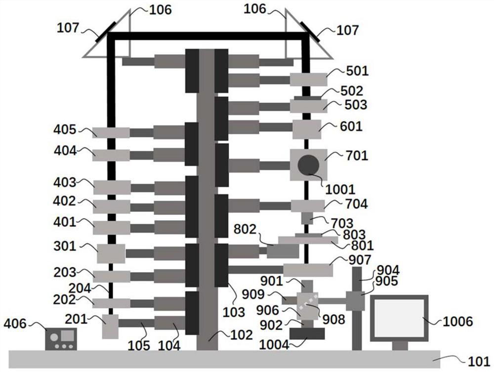
[0034] An optical tweezers device based on a liquid crystal device for experimental teaching and scientific research, such as figure 1 , including an optical component support frame and a light source module installed on the optical component support frame, a beam expander module, a polarization control module, a wavefront modulation module, a beam reduction module, a focusing module, a sample adjustment module, a microscope module and a monitoring and recording module.

[0035] The optical component support frame includes an optical breadboard 101 and a vertical support 102, the vertical support 102 is vertically arranged on the optical breadboard 101, and several sliding bases are movable along the normal direction of the optical breadboard 101 on the vertical support 102, The quantity of reflecting mirror 107 is two, and every reflecting mirror 107 is fixed on one of them sliding base by reflecting mirror frame 106, and two reflecting mirrors 107 are arranged symmetrically a...

Embodiment 2

[0059] In this example, if figure 1 , the optical component support frame also includes two reflectors 107 positioned at the top of the vertical support 102, each reflector 107 is fixed on one of the sliding bases by the reflector frame 106, and the two reflectors 107 are arranged symmetrically about the vertical support 102 ;

[0060] If the designed optical path is long, divide the multiple optical components into two parts, the light source module, the beam expander module, the polarization control module and one of the reflectors 107 are located on the same side of the vertical support 102, the wavefront modulation module, the beam shrinker module, The focus module, the sample adjustment module, the microscope module, the monitoring and recording module, and another reflector 107 are located on the same side of the vertical support 102, and the light beams emitted by the optical components on one side of the vertical support 102 pass through the two reflectors 107 After r...


PUM


Abstract

The invention relates to an optical tweezers device based on a liquid crystal device for experimental teaching and scientific research. The optical tweezers device comprises an optical component support frame, and a light source module, a beam expanding module, a polarization control module, a wavefront modulation module, a beam shrinking module, a focusing module, a sample adjusting module, a microscopic module and a monitoring and recording module which are mounted on the optical component support frame, the wavefront modulation module comprises a second adjustable diaphragm (501), a patterned orientation liquid crystal wave plate (502) and a liquid crystal wave plate adjusting frame (503), the second adjustable diaphragm (501) and the liquid crystal wave plate adjusting frame (503) are movably arranged on the optical component supporting frame, and the patterned orientation liquid crystal wave plate (502) is arranged on the liquid crystal wave plate adjusting frame (503). And the patterned orientation liquid crystal wave plate (502) has patterned orientation. Compared with the prior art, the optical tweezers experimental teaching and scientific research requirements are met, the operability is high, the intuition is high, and the structure is compact.

Description

technical field [0001] The invention relates to the field of optical technology, in particular to an optical tweezers device based on a liquid crystal device used for experimental teaching and scientific research. Background technique [0002] Optical tweezers, also known as single-beam gradient force optical traps, are the tweezers that are used to hold objects in daily life, and they can be clamped by applying a certain force through the tweezers. The optical tweezers that capture tiny particles is a special light field. When this light field interacts with an object, the entire object is affected by light to achieve the effect of being clamped, and then the object can be moved by moving the light beam. If the center of the light field is used to delimit an area of ​​a few microns, it will be observed that once the photons step into this restricted area, they will automatically and quickly fall to the center of the light, which shows that the light field has the effect of ...

Claims


Application Information

Patent Timeline
Patent Type & Authority Applications(China)
IPC IPC(8): G09B23/22
Inventor 王骁乾
Owner EAST CHINA UNIV OF SCI & TECH
Why Eureka
Try Eureka