Reinforced soil retaining dam

A technology for retaining dams and reinforced soil, which is applied in the direction of dams, barrages, and water conservancy projects, and can solve the problems of project investment that cannot overflow the dam body, high requirements for the nature of the project, and increased project investment, so as to solve the problems of overflow and water consumption. Energy problems, improvement of deformation conditions, and the effect of reducing engineering investment

Pending Publication Date: 2022-04-12
CHINA HYDROELECTRIC ENGINEERING CONSULTING GROUP CHENGDU RESEARCH HYDROELECTRIC INVESTIGATION DESIGN AND INSTITUTE
View PDF0 Cites 1 Cited by
  • Summary
  • Abstract
  • Description
  • Claims
  • Application Information

AI Technical Summary

Problems solved by technology

[0002] In hydropower and water conservancy projects, it is often necessary to build dams to permanently or temporarily block river water. Among them, earth-rock dams are the oldest type of dams. They are dams filled with local materials such as soil and stone. Usually, the dam body formed by soil filling can be used for anti-seepage. This type of earth-rock dam has high requirements on the engineering properties of the soil, which often leads to poor applicability; in addition, in order to ensure the stability of the upstream and downstream dam slopes , the cross-sectional shape of an earth-rock dam is often trapezoidal; on the other hand, due to the characteristics of soil softening in contact with water and deterioration of engineering performance, the body of an earth-rock dam often cannot overflow and discharge floods, and it is often necessary to set up additional overflow tunnels or spillways. flow facilities, and thus increase more engineering investment. In summary, conventional earth-rock dam structures have disadvantages such as poor adaptability, inability to overflow the dam body, and large engineering investment.

Method used


Image

  • Reinforced soil retaining dam
  • Reinforced soil retaining dam

Examples


Embodiment Construction

[0017] The present invention will be further described below in conjunction with the accompanying drawings.

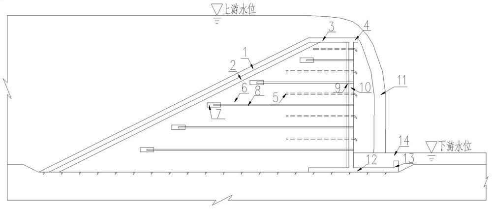
[0018] like figure 1 As shown, the present invention includes a retaining dam base 6 made of reinforced soil, and the upstream surface of the retaining dam base 6 is a slope whose top is inclined downstream, and the upstream surface of the retaining dam base 6 is in turn from the inside to the outside. A cushion layer 2 and a slope concrete seepage-proof panel 1 are arranged, and a top concrete seepage-proof panel 3 is arranged on the top of the base 6 of the retaining dam. The top concrete seepage-proof panel 3 is combined with the slope concrete seepage-proof panel 1 to form a whole Strict anti-seepage overall, the downstream end of the top concrete anti-seepage panel 3 is provided with a sill 4, the downstream slope of the retaining dam base 6 is provided with a concrete support panel 10, and the downstream slope of the retaining dam base 6 is an upright slope. The...


PUM


Abstract

The invention relates to a reinforced soil retaining dam, and belongs to the field of retaining dams in water conservancy and hydropower engineering. The water retaining dam comprises a water retaining dam base body formed by piling reinforced soil, the upstream face of the water retaining dam base body is a slope with the top end inclining to the downstream, a cushion layer and a slope surface concrete anti-seepage face plate are sequentially arranged on the upstream face of the water retaining dam base body from inside to outside, a top concrete anti-seepage face plate is arranged at the top of the water retaining dam base body, and a top concrete anti-seepage face plate is arranged at the bottom of the top concrete anti-seepage face plate. The top concrete anti-seepage panel and the slope concrete anti-seepage panel are combined into a whole, a flip bucket is arranged at the downstream end of the top concrete anti-seepage panel, and a concrete supporting panel is arranged on the downstream slope of the water retaining dam base body. The reinforced soil retaining dam provided by the invention can overflow, and is simple in structure, high in adaptability and low in investment cost.

Description

technical field [0001] The invention relates to a reinforced earth retaining dam, which belongs to the field of retaining dams in water conservancy and hydropower engineering. Background technique [0002] In hydropower and water conservancy projects, it is often necessary to build dams to permanently or temporarily block river water. Among them, earth-rock dams are the oldest type of dams. They are dams filled with local materials such as soil and stone. The dam body formed by soil filling can often be used to prevent seepage. This type of earth-rock dam has high requirements on the engineering properties of soil, which often leads to poor applicability. In addition, in order to ensure the stability of the upstream and downstream dam slopes , the cross-sectional shape of the earth-rock dam is often trapezoidal; on the other hand, due to the characteristics of soil softening in contact with water and poor engineering performance, the dam body of earth-rock dam often cannot o...

Claims


Application Information

Patent Timeline
Patent Type & Authority Applications(China)
IPC IPC(8): E02B7/06E02B3/12E02B3/14E02B3/16E02B8/06
Inventor 杜震宇刘跃陈军谢金元唐碧华
Owner CHINA HYDROELECTRIC ENGINEERING CONSULTING GROUP CHENGDU RESEARCH HYDROELECTRIC INVESTIGATION DESIGN AND INSTITUTE
Why Eureka
Try Eureka