Detachable wireless self-powered mouse based on rotary power generation

A self-powered, detachable technology, applied in the field of wireless mouse, can solve the problems of non-detachable power supply unit, small upper limit of power generation, affecting the size and weight of equipment, etc., to achieve lightweight design, increase total output voltage, increase The effect of generating power

Active Publication Date: 2022-05-31
HUAZHONG UNIV OF SCI & TECH
View PDF10 Cites 0 Cited by
  • Summary
  • Abstract
  • Description
  • Claims
  • Application Information

AI Technical Summary

Problems solved by technology

However, the structural design of the self-powered system is affected by the inertia of the conductor and cannot cope with the violent movement of the mouse, resulting in a small upper limit for the power generation
[0004] In general, limited by the structure and energy collection method, the existing wireless self-powered mouse has low power generation and low power generation efficiency, and cannot continuously supply power to the mouse
In addition, most of the power supply units in existing wireless self-powered mice cannot be disassembled, which seriously affects the size and weight of the equipment, and does not meet the needs of the lightweight design of the mouse

Method used


Image

  • Detachable wireless self-powered mouse based on rotary power generation
  • Detachable wireless self-powered mouse based on rotary power generation
  • Detachable wireless self-powered mouse based on rotary power generation

Examples


Embodiment Construction

[0033] In order to make the object, technical solution and advantages of the present invention clearer, the present invention will be further described in detail below in conjunction with the accompanying drawings and embodiments. It should be understood that the specific embodiments described here are only used to explain the present invention, not to limit the present invention. In addition, the technical features involved in the various embodiments of the present invention described below can be combined with each other as long as they do not constitute a conflict with each other.

[0034] In the present invention, the terms "first", "second" and the like (if any) in the present invention and drawings are used to distinguish similar objects, and are not necessarily used to describe a specific order or sequence.

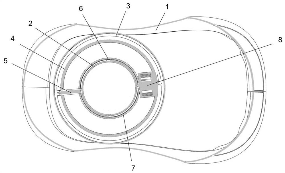
[0035] figure 1 A top view of a detachable wireless self-powered mouse based on rotation power generation provided by an embodiment of the present invention. ref...


PUM


Abstract

The invention discloses a detachable wireless self-powered mouse based on rotary power generation, and belongs to the technical field of wireless mouses.The detachable wireless self-powered mouse comprises a mouse shell and a detachable power generation unit arranged in the mouse shell, and the detachable power generation unit comprises a rotor, two hemispherical spherical shells and a power generation unit, the two hemispherical spherical shells are detachably connected through a first buckle; the rotor bracket is a circular tube of which one end is fixed on the bottom plate of the mouse shell, and an annular groove is formed in the circumferential direction of the inner wall of the rotor bracket; the other end of the annular support is located in the annular groove, and the other end of the rotating shaft is connected with the rotor; the coils are arranged along the outer surface of the coil bracket; under the action of external force, the rotor, the rotating shaft and the annular support jointly rotate in the circumferential direction of the annular groove, the rotor rotates around the rotating shaft, and induced current is generated in the coil to generate electricity. The power generation power and the power generation amount of the wireless self-powered mouse are improved, and the light design is achieved.

Description

technical field [0001] The invention belongs to the technical field of wireless mouse, and more specifically relates to a detachable wireless self-powered mouse based on rotation power generation. Background technique [0002] With the rapid development of human-computer interaction technology, various types of human-computer interaction devices emerge in endlessly. The mouse is a common computer input device, and the wireless mouse uses wireless technology to communicate with the computer, thereby eliminating the shackles of wires. Most wireless mice are powered by batteries. Due to the limited battery capacity, the battery life of wireless mice varies, which causes great inconvenience to users. At present, the common mouse self-power supply system design concentrates energy collection on the human body using the mouse to do work, but in actual use, the human body uses the mouse to do very little work, and the energy collected for this purpose is not enough to independentl...

Claims


Application Information

Patent Timeline
Patent Type & Authority Applications(China)
IPC IPC(8): G06F3/0354H02K7/18H02K1/2706H02K1/30H02K3/47H02K3/28H02K7/118H02K11/04H02J7/14
CPCG06F3/03543H02K7/1853H02K1/2706H02K1/30H02K3/47H02K3/28H02K7/118H02J7/14Y02B40/00
Inventor 顾天逸彭晗吕鑫盛陈益华刘先超肖洪飞孙寒燚
Owner HUAZHONG UNIV OF SCI & TECH
Why Eureka
Try Eureka