Array antenna base station device and radio transmission method

An array antenna and base station technology, applied in the directions of antenna, wireless communication, selection device, etc., can solve the problems of communication terminal interference, deterioration of reception quality of the second communication terminal and the third communication terminal, etc.

Inactive Publication Date: 2002-11-20
PANASONIC CORP
View PDF2 Cites 1 Cited by
  • Summary
  • Abstract
  • Description
  • Claims
  • Application Information

AI Technical Summary

Problems solved by technology

As a result, the reception quality of the second communication terminal and the third communication terminal deteriorates
[0006] Therefore, in the conventional CDMA-based digital mobile communication system, when the base station performs high-speed data communication with a predetermined communication terminal, there is a problem that large interference occurs to communication terminals other than the communication terminal.

Method used


Image

  • Array antenna base station device and radio transmission method
  • Array antenna base station device and radio transmission method
  • Array antenna base station device and radio transmission method

Examples


Embodiment 1

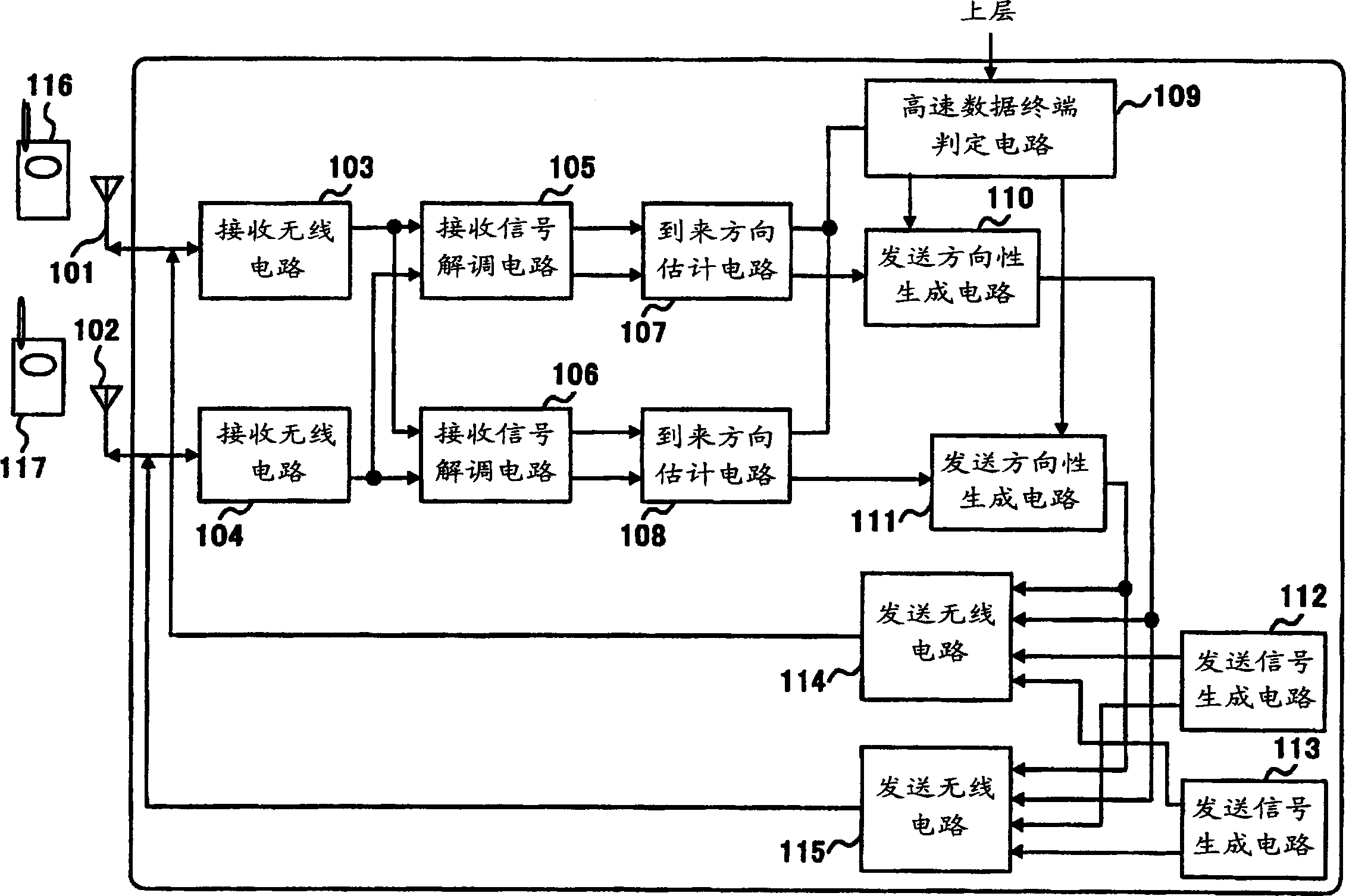
[0040] figure 1 A block diagram showing the configuration of the array antenna base station apparatus according to Embodiment 1 of the present invention. In this embodiment, as an example, a case where a base station apparatus performs wireless communication with two communication terminals, communication terminal 116 and communication terminal 117, will be described.

[0041] exist figure 1 Among them, the receiving radio circuit 103 and the receiving radio circuit 104 convert signals (received signals) received from the antenna 101 and the antenna 102 into baseband signals, respectively.

[0042] Reception signal demodulation circuit 105 and reception signal demodulation circuit 106 generate demodulated signals by performing demodulation processing such as despreading using baseband signals from reception radio circuit 103 and reception radio circuit 104 .

[0043] The direction of arrival estimation circuit 107 estimates the direction of arrival of the communication termi...

Embodiment 2

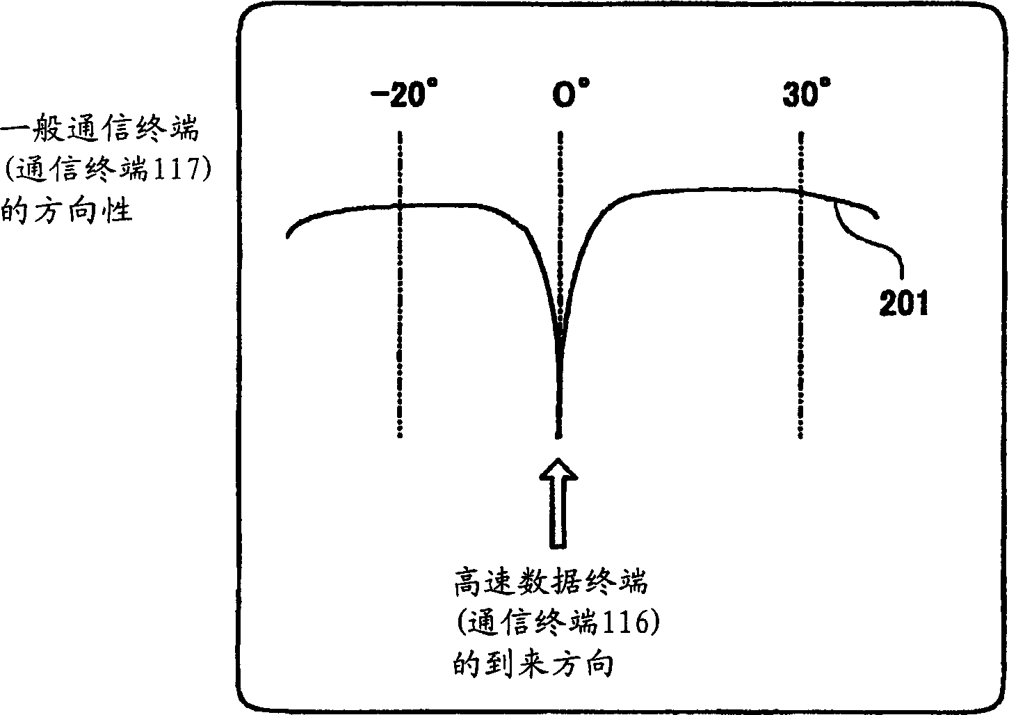
[0061] In this embodiment, a case will be described in which the transmission directivity of a general communication terminal is shifted so that the beam null point faces the direction of arrival of a high-speed data communication terminal. Below, refer to image 3 The array antenna base station apparatus of this embodiment will be described.

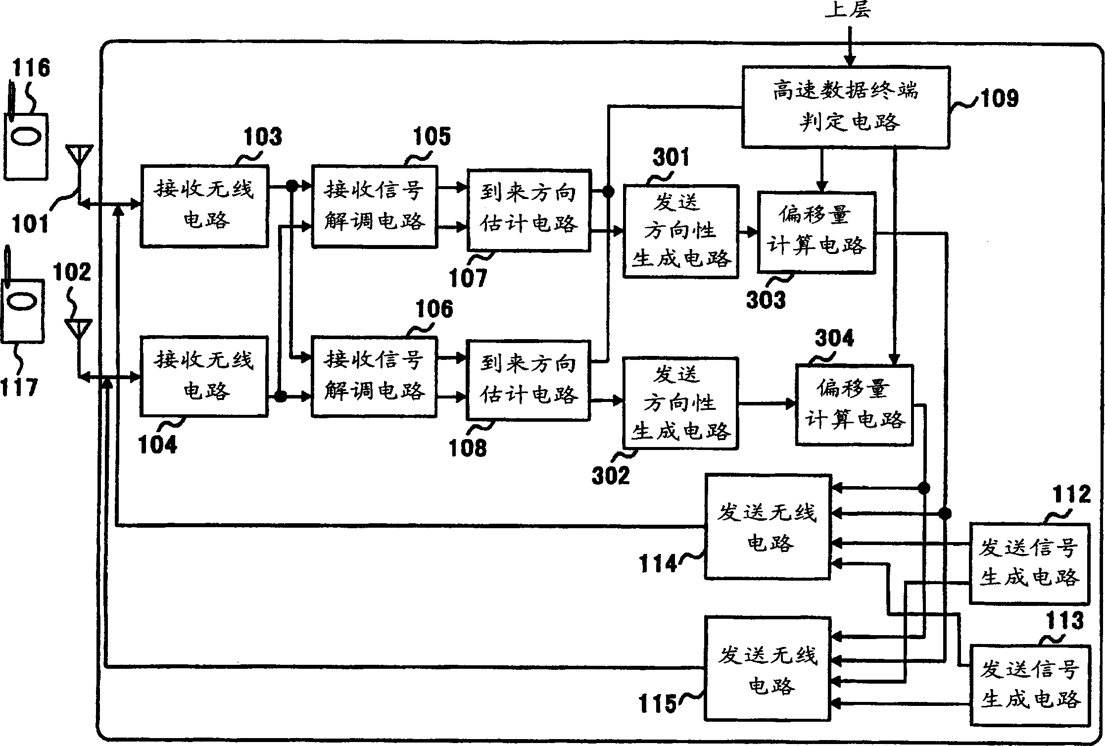
[0062] image 3 A block diagram showing the configuration of an array antenna base station apparatus according to Embodiment 2 of the present invention. for image 3 In and embodiment 1 ( figure 1 ) with the same structure as figure 1 The symbols with the same structure in , and detailed descriptions are omitted.

[0063] exist image 3 Among them, the transmission directivity generation circuit 301 and the transmission directivity generation circuit 302 generate the transmission directivities of the communication terminal 116 and the communication terminal 117, respectively. The transmission directivity generation circuit 301 an...

Embodiment 3

[0072] In this embodiment, a case where there are a plurality of high-speed data communication terminals will be described. Below, refer to Figure 5 The array antenna base station apparatus of the third embodiment will be described. Figure 5 It is a block diagram showing the configuration of an array antenna base station apparatus according to Embodiment 3 of the present invention. for Figure 5 and Example 1 ( figure 1 ) with the same structure as figure 1 The same reference numerals are used for the structures, and detailed descriptions are omitted.

[0073] exist Figure 5 Among them, the high-speed data terminal number determination circuit 502 detects the number of high-speed data communication terminals by using the information from high-level high-speed data communication terminals, and sends the detection result to the high-speed data terminal direction determination circuit 501. Moreover, in the high-speed data terminal direction judging circuit 501 based on t...


PUM


Abstract

An array antenna base station device, in which transmission directivity generation circuits 110 and 111 are connected to a communication terminal that is a target of transmission directivity generation (that is, communication terminal 116 in transmission directivity generation circuit 110, and communication terminal 116 in transmission directivity generation circuit 111 In the case where the communication terminal 117) is a high-speed data communication terminal, a transmission direction is generated such that the directivity faces the direction of arrival of a signal transmitted from the high-speed data communication terminal. Conversely, when the communication terminal to be the target of the transmission directivity is a communication terminal performing general communication, the beam null point is generated so that the signal transmitted from the high-speed data communication terminal faces the arrival direction.

Description

technical field [0001] The present invention relates to a communication device used in a CDMA (Code Division Multiple Access: Code Division Multiple Access) digital mobile communication system, and more particularly to a base station device for high-speed data communication using an array antenna. Background technique [0002] In recent years, in a digital mobile communication system, in order to realize high-speed data communication, a method of multi-valued modulation and transmission of data has been proposed. [0003] However, in the conventional CDMA-based digital mobile communication system, there are the following problems. Regarding these problems, a case where a base station performs wireless communication with a plurality of (here, for example, three communication terminals, a first communication terminal to a third communication terminal, for example) communication terminal will be described as an example. In addition, it is assumed that ...

Claims


Application Information

Patent Timeline
Patent Type & Authority Applications(China)
IPC IPC(8): H01Q3/26H04B7/06H04B7/08H04B7/10H04B7/26H04W16/28
CPCH01Q3/26H01Q3/2605H04B7/0617H04B7/086H04W16/28
Inventor 青山高久三好宪一上丰树
Owner PANASONIC CORP
Why Eureka
Try Eureka