Short-circuit fault current limitter

A technology of fault current limiter and short-circuit fault, which is applied in the direction of circuit devices, emergency protection circuit devices, and protection against overcurrent. Cost, high reliability, and the effect of improving current limiting capability

Inactive Publication Date: 2006-11-29
INST OF ELECTRICAL ENG CHINESE ACAD OF SCI
View PDF2 Cites 16 Cited by
  • Summary
  • Abstract
  • Description
  • Claims
  • Application Information

AI Technical Summary

Problems solved by technology

At the same time, the current flowing through the bias power supply is often 2 to 3 times the grid current, and must meet the requirements of the current change

Method used


Image

  • Short-circuit fault current limitter
  • Short-circuit fault current limitter
  • Short-circuit fault current limitter

Examples


Embodiment Construction

[0026] The present invention will be further described below in conjunction with accompanying drawing and specific embodiment:

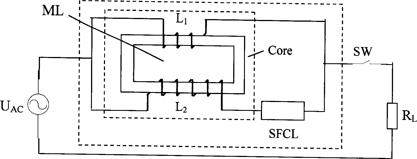
[0027] Such as figure 2 As shown, Embodiment 1 of the present invention is a single-phase short-circuit fault current limiter. consists of a small superconducting fault current limiter SFCL and a winding L 1 , L 2 The transformer ML composed of the rectangular closed iron core Core constitutes a single-phase short-circuit fault current limiter. One winding L of transformer ML 2 in series with the superconducting fault current limiter SFCL, and then with winding L 1 in parallel. Among them, the two windings L 1 , L 2 The magnetic potential is opposite. The superconducting fault current limiter SFCL can be a resistive or DC reactive type superconducting fault current limiter. SW is circuit breaker, U AC for line AC power, R L is the load equivalent resistance.

[0028] image 3 Shown is the impedance characteristic waveform of the superco...


PUM


Abstract

This invention relates to a current limiter of short-circuit fault, which applies the mutual inductance theory of magnets and the impedance variance property of superconductive materials in the fault limit composed of a superconductive faulty limiter and a mutual inductor, a winding of which is serial to a superconductive fault limiter then parallel to another winding to adjust mutual inductance and limit fault current by the property that the impedance of the superconductive limiter varies along with the change of current.

Description

technical field [0001] The invention relates to a short-circuit fault current limiter, in particular to a fault current limiter for transmission and distribution networks. Background technique [0002] With the rapid development of the national economy, the society's demand for electricity continues to increase, which drives the continuous development of the power system. The capacity of single machines and power plants, the capacity of substations, and the load of cities and industrial centers continue to increase, which makes the interconnection of power systems , the level of short-circuit current in the power grid at all levels is increasing continuously, and the destructiveness of short-circuit faults to the power system and its connected electrical equipment is also increasing. Moreover, while the demand for electric energy is increasing day by day, people also put forward higher requirements for power quality, power supply reliability and security. However, the trans...

Claims


Application Information

Patent Timeline
IPC IPC(8): H02H9/02H02H3/08
CPCY02E40/69Y02E40/60
Inventor 肖立业张志峰林良真林玉宝王子凯赵彩宏惠东
Owner INST OF ELECTRICAL ENG CHINESE ACAD OF SCI
Why Eureka
Try Eureka