Method for manufacturing gear wheel in large diameter

A processing method and large-diameter technology, which can be applied to components with teeth, metal processing equipment, gear tooth manufacturing devices, etc., can solve the problems of high processing cost, difficult to find equipment, and processing difficulty, and achieve the purpose of reducing processing costs and saving energy. The effect of removing processing equipment and increasing carrying capacity

A processing method and large-diameter technology, which can be applied to components with teeth, metal processing equipment, gear tooth manufacturing devices, etc., can solve the problems of high processing cost, difficult to find equipment, and processing difficulty, and achieve the purpose of reducing processing costs and saving energy. The effect of removing processing equipment and increasing carrying capacity

CN1872474AInactive Publication Date: 2006-12-06SHANGHAI HEAVY MACHINERY PLANT

Image

  • Method for manufacturing gear wheel in large diameter
  • Method for manufacturing gear wheel in large diameter
  • Method for manufacturing gear wheel in large diameter

Examples


Embodiment Construction

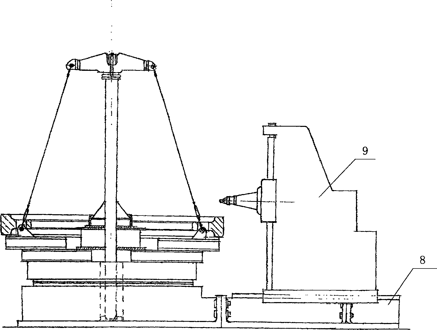
[0019] figure 1 Shown is the structure of the device used in the processing method of a large-diameter gear of the present invention. It includes a work table, guide rails 7 and a gear hobbing machine 8 .

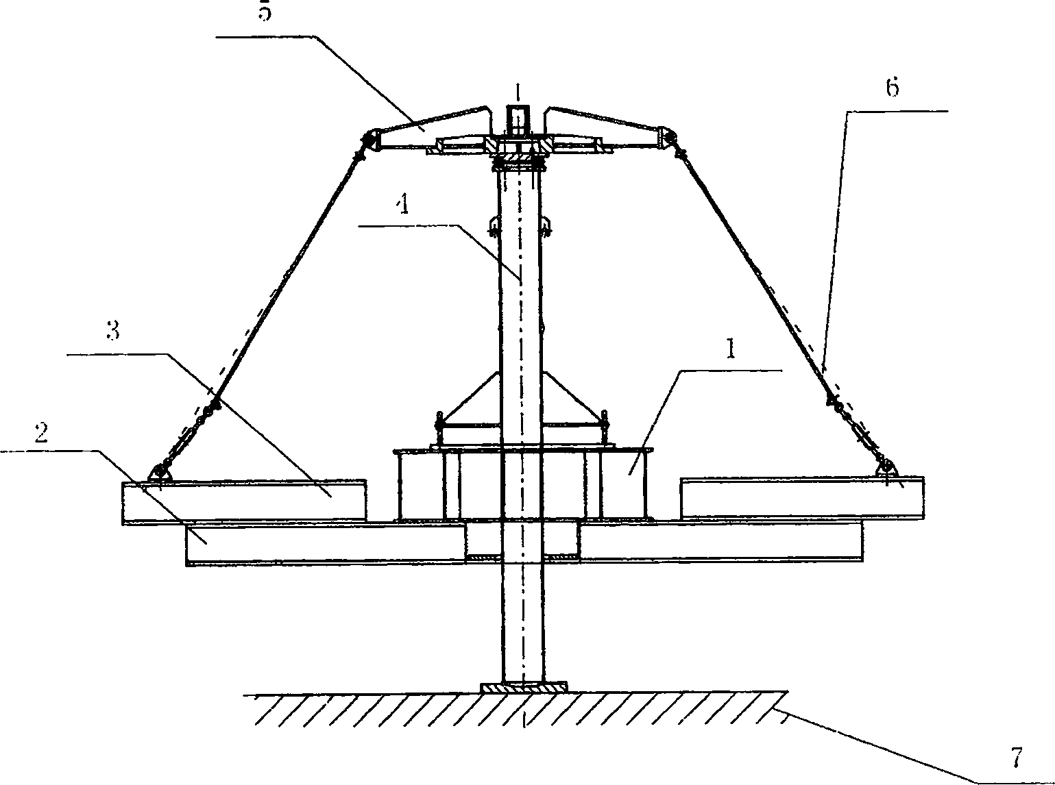
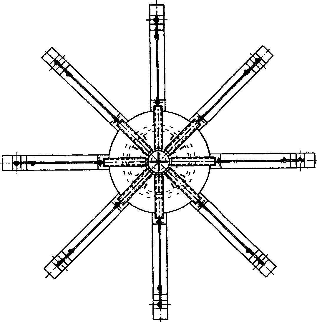
[0020] figure 2 Shown is a side view of the structure of the hobbing machine table top modified for use of the present invention. An extension beam is installed on the work surface 1, and the extension beam is divided into a first-level extension beam 2 and a second-level extension beam 3. The first-level extension beam 2 is directly installed on the work surface 1, and the second-level extension beam 3 is installed on the first-level extension beam 2. Above; the extension beam takes the center of the worktable 1 as the center of a circle and is radial with a uniform angle, such as image 3 Shown; Pole device 4 is vertically installed, and passes through the center of work surface 1, and its lower end acts on ground 7; Cable-stayed device comprises cable-stayed arm 5 an...


PUM


Abstract

A technology for machining a large-diameter gear features that the guide tracks of gear hobbing machine is elongated for meeting the size requirement of large-diameter gear and the extending beams, vertical post unit and oblique pull unit are additionally installed onto bench for increasing its load bearing power.

Description

technical field [0001] The invention relates to a method for processing large-diameter gears, in particular to a method for processing large-diameter gears with a smaller type hobbing machine. Background technique [0002] The diameter of most large gears of heavy machinery and equipment can reach 5-6 meters, which can be regarded as very large, but there are also individual super-large gears whose diameter needs to reach a larger size, which brings considerable problems in processing. Great difficulty. To be able to process gears with a diameter of 5 to 6 meters already requires a very large gear hobbing machine, and if it is necessary to process larger gears, it is difficult to find corresponding equipment, and the price is also quite expensive. Although there is a need for such a large-sized gear, the quantity required is very limited. If you buy a very expensive equipment for this reason, it will be useless after processing a few large gears. Not only the processing co...

Claims


Application Information

Patent Timeline
06 Dec 2006
Publication
CN1872474A
IPC
B23F5/22; B23F23/02
Inventors
刘巽强; 李友发