High voltage electric-saver

A technology of power saving and high voltage section, applied in the direction of adjusting electrical variables, instruments, electrical components, etc., can solve the problem of high voltage, and achieve the effect of prolonging the service life, reducing maintenance costs, and reducing electricity bills

A technology of power saving and high voltage section, applied in the direction of adjusting electrical variables, instruments, electrical components, etc., can solve the problem of high voltage, and achieve the effect of prolonging the service life, reducing maintenance costs, and reducing electricity bills

CN1925255AInactive Publication Date: 2007-03-07上海璞圆节能科技有限公司

Image

  • High voltage electric-saver
  • High voltage electric-saver
  • High voltage electric-saver

Examples


Embodiment Construction

[0023] The present invention will be further described in detail in conjunction with the accompanying drawings and embodiments.

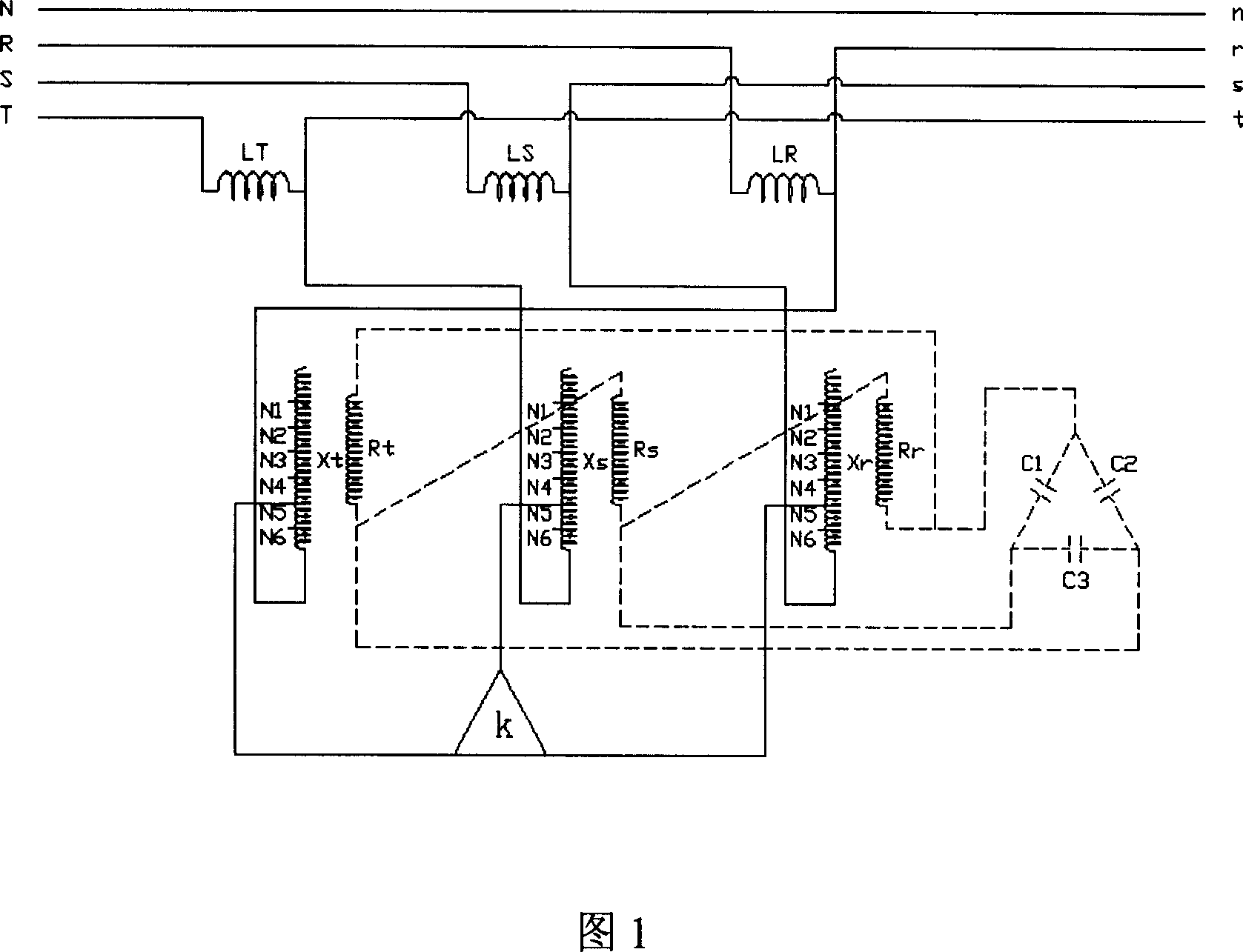
[0024] Referring to Figure 1, LT, LS, and LR are three-phase main circuit reactance coils, which are connected in series in the high-voltage line (the left side of the high-voltage line in the figure is the input end, and the right side is the output end), which can filter out harmonics and reduce voltage. ; Xt, Xs, Xr are three-phase voltage adjustment coils, Rt, Rs, Rr are phase adjustment coils, C1, C2, C3 are power capacitors, and K is a voltage coil tap changeover switch (modified with a power transformer on-load tap changer) , select among the taps N1, N2, N3, N4, N5 and N6 of the voltage regulating coil through the switch, so that the main coils LT, LS, LR can sense different voltages to ensure that the main circuit is continuously powered, and it can be done with a small current Control the large current of the main circuit.
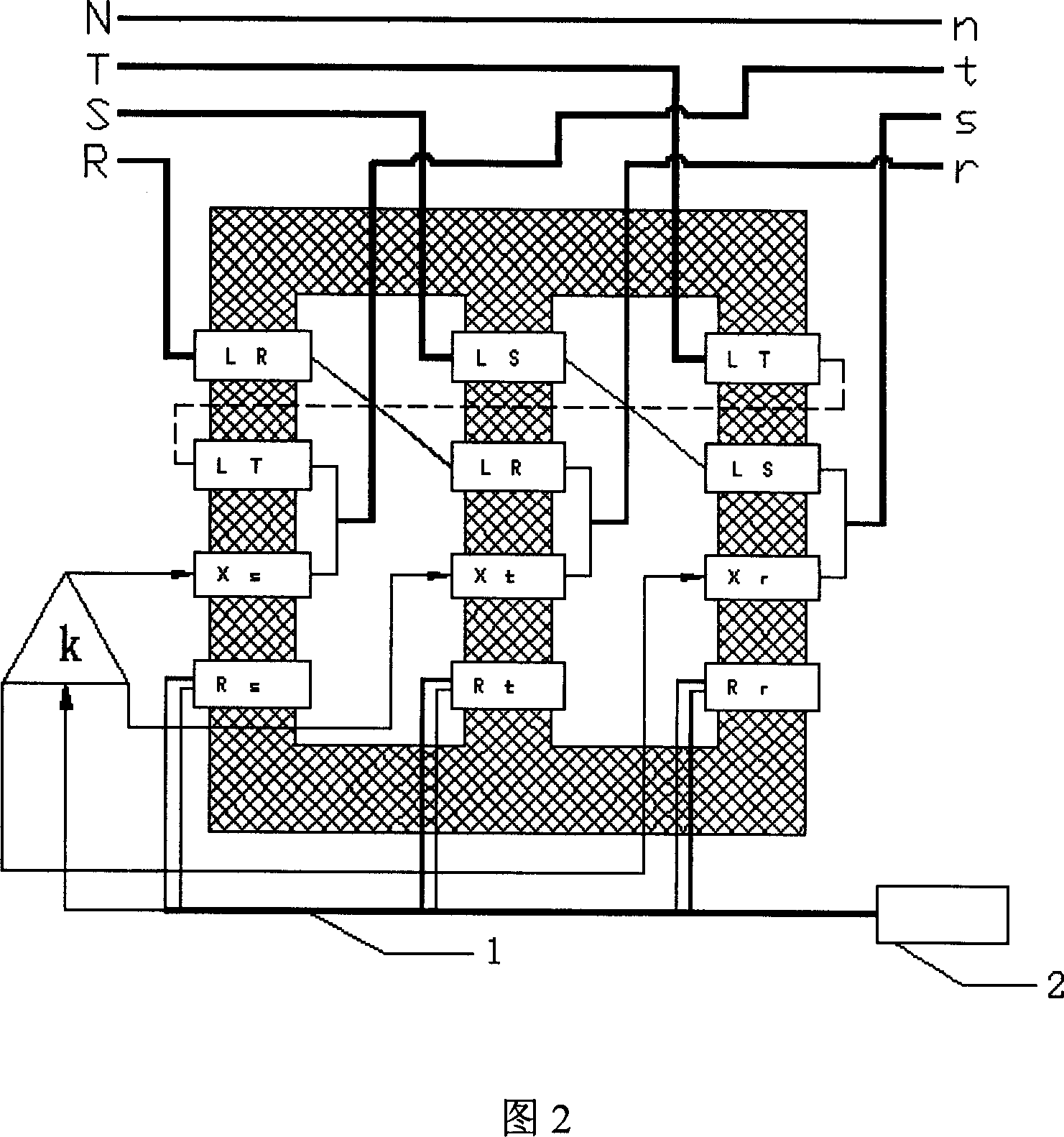
[0025] Referr...


PUM


Abstract

This invention discloses one high voltage energy saving device, which comprises the following parts: main loop electricity resistance coil into high voltage circuit; voltage to change main loop electricity coil two ends of conversion switch controller from couple drawer transducer coil and main loop coil; processing independent balance phase adjusting coil on same transducer iron chip. The coil has high voltage resistance filter to provide stable voltage within economical range with three phase current balance.

Description

technical field [0001] The invention relates to a voltage stabilizing and power saving device, in particular to a voltage stabilizing and power saving device applied to high voltage lines. Background technique [0002] With the development of the electric power industry and the improvement of the country's rural power grid reconstruction project, the phenomenon of low voltage at the end of the power grid has been generally improved. However, the subsequent problem is that the voltage of the power grid is generally high, especially when the voltage of 380V rises to 425V when the power consumption is low. [0003] At present, there are not many energy-saving equipment used in high-voltage lines on the market. Only a few manufacturers in Japan and Taiwan produce high-voltage reactance filter equipment, but their functions are single, and the voltage of the reactors connected in series cannot be adjusted, so the energy-saving effect is very poor. The power saver of the low-volt...

Claims


Application Information

Patent Timeline
07 Mar 2007
Publication
CN1925255A
IPC
H02J3/00; H02J3/01; H02J3/26; G05F1/12
CPC
Y02E40/50; Y02E40/40
Inventors
戴如宏