Pressure compensation control of a fixed displacement pump in a pumping and metering system and associated method

a technology of pressure compensation control and fixed displacement, applied in the field of fuel system, can solve problems such as limited pressure rippl

Active Publication Date: 2018-08-07
EATON INTELLIGENT POWER LTD
View PDF21 Cites 4 Cited by
  • Summary
  • Abstract
  • Description
  • Claims
  • Application Information

AI Technical Summary

Benefits of technology

[0015]The high speed centrifugal pump is always wetted and operating essentially as a high pressure boost stage for the fixed displacement pump thus eliminating the need for turning the high speed pump on and off, or drying out the high speed pump.
[0020]An inducer stage is provided in one modification and driven at a reduced rotational speed to operatively improve inlet performance characteristics of the centrifugal pump.
[0026]The method may include using an inducer driven at a reduced rotational speed to operatively improve inlet performance characteristics of the centrifugal pump.
[0031]Compensation of the fixed displacement pump using hydromechanical pressure results in better system stability and a faster response to system disturbances than a system that uses an electronic control.

Problems solved by technology

Further, the centrifugal pump is generally lightweight, is deemed to have an extended life, has limited pressure ripple, and is generally conducive for a wide array of downstream uses.
Engine start is one area because the high speed centrifugal pump does not provide the required elevated fuel pressures for start-up until the engine speed has increased to a certain level.

Method used


Image

  • Pressure compensation control of a fixed displacement pump in a pumping and metering system and associated method
  • Pressure compensation control of a fixed displacement pump in a pumping and metering system and associated method
  • Pressure compensation control of a fixed displacement pump in a pumping and metering system and associated method

Examples


Embodiment Construction

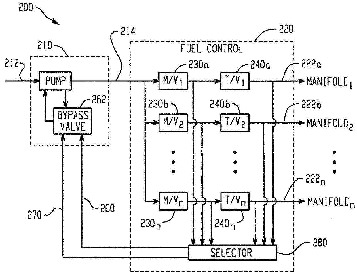
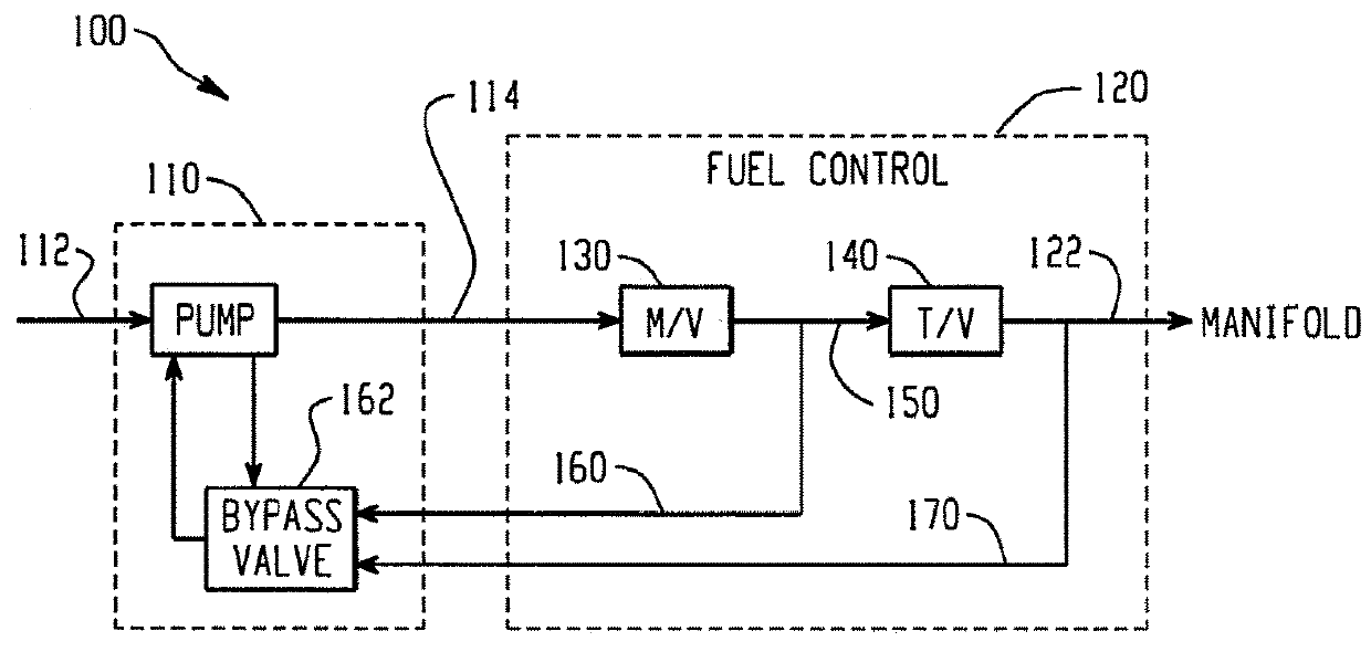
[0038]FIG. 1 is a schematic representation of a fuel system or pumping and metering system 100, and in particular is representative of a single metering loop. The system 100 includes a pump unit 110 such as a fuel pump for an aircraft engine that receives fluid from an upstream source (not shown) as represented by reference numeral 112 and delivers pressurized fluid 114 to a downstream fuel control 120 that controls fluid for one or more downstream uses represented by reference numeral 122. In the broadest sense, the fuel control 120 includes a metering valve 130 and a throttling valve 140.

[0039]The metering valve 130 receives the pressurized fluid 114 from the pump unit 110 and meters or delivers pressurized fluid 150 downstream to the throttling valve 140. The pump unit 110, and typically one used as a fuel pump for an aircraft engine, for example, includes a centrifugal pump for the reasons noted in the Background. As further described above, additional use of a fixed displacemen...


PUM


Abstract

A fuel system includes a pump unit having at least a fixed displacement pump supplying pressurized flow. A fuel control assembly receives flow from the pump unit and includes at least one metering valve and at least one throttling valve. A control (bypass valve control) for the fixed displacement pump receives first and second pressure signals indicative of a pressure differential across the throttling valve, or across the metering valve / throttling valve combination, for altering output from the fixed displacement pump in response to the pressure differential. In other embodiments, the pump unit includes a centrifugal pump and a fixed displacement pump that can be fully or partially redundant depending on sizing of the pumps, and the system requirements.

Description

[0001]This national stage application is a submission under 35 U.S.C. 371 of PCT International Patent Application No. PCT / US2013 / 039026, filed on 01 May 2013, and claims the priority benefit of US Provisional Application Nos. 61 / 641,088, filed on May 01, 2012; 61 / 664,422, filed on Jun. 26, 2012; 61 / 664,447, filed on Jun. 26, 2012; and 61 / 757,281, filed on Jan. 28, 2013, the disclosures of which are incorporated herein by reference.BACKGROUND[0002]The present disclosure relates to a fuel system, and more particularly to a system that includes at least a supplemental fixed displacement pump. It finds particular application in conjunction with a fuel metering system, and will be described with particular reference thereto. However, it is to be appreciated that the present exemplary embodiment is also amenable to other like applications.[0003]Generally, a high speed centrifugal pump is desired in a fuel system because of the benefits related to power consumption. Further, the centrifuga...

Claims


Application Information

Patent Timeline
Patent Type & Authority Patents(United States)
IPC IPC(8): F04D15/00F02C9/30F02C7/232F04B23/10F04B23/14F02C7/236F04D13/06F04D13/14F04B49/08
CPCF04D15/0072F02C7/236F02C9/30F04B23/10F04B23/14F04B49/08F04D13/06F04D13/14F04D15/0011F04D15/0022F04D15/0066F02C7/232F05B2270/3015F05B2210/11F05B2270/1033
Inventor NYZEN, ROBERTCLEMENTS, MARTIN A.
Owner EATON INTELLIGENT POWER LTD
Why Eureka
Try Eureka