Printing apparatus and platen

a printing apparatus and platen technology, applied in printing, other printing apparatus, etc., can solve the problems of reducing the quality of an image at the floating portion of the sheet, the inability to suppress the leading end of the sheet, and the sheet smear, etc., to achieve the effect of suppressing the floating or flexure of the sheet and high quality

Active Publication Date: 2018-09-11
CANON KK
View PDF35 Cites 1 Cited by
  • Summary
  • Abstract
  • Description
  • Claims
  • Application Information

AI Technical Summary

Benefits of technology

[0006]An object of the present invention is to provide a printing apparatus capable of suppressing floating or flexure of a sheet so as to obtain an image of a high quality in marginless printing.
[0007]Moreover, another object of the present invention is to provide a printing apparatus capable of securely performing four-side marginless printing with respect to a cut sheet, and a platen.

Problems solved by technology

Thus, the floating of the leading end of the sheet cannot be suppressed at the time of the introduction of the sheet, and thus, ink is landed on the sheet that remains floating.
As a consequence, there is a possibility that the quality of an image is reduced at the floating portion of the sheet or the sheet smears due to the contact of the sheet with a printhead.

Method used


Image

  • Printing apparatus and platen
  • Printing apparatus and platen
  • Printing apparatus and platen

Examples


first embodiment

1. Outline of Apparatus

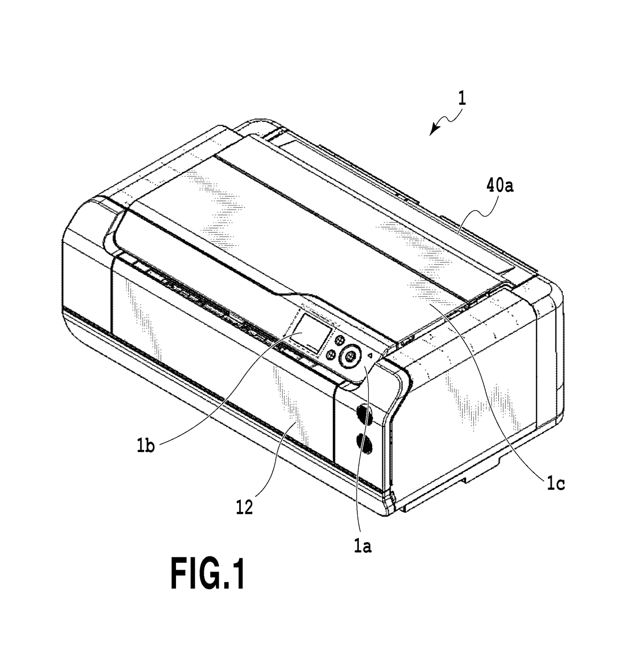
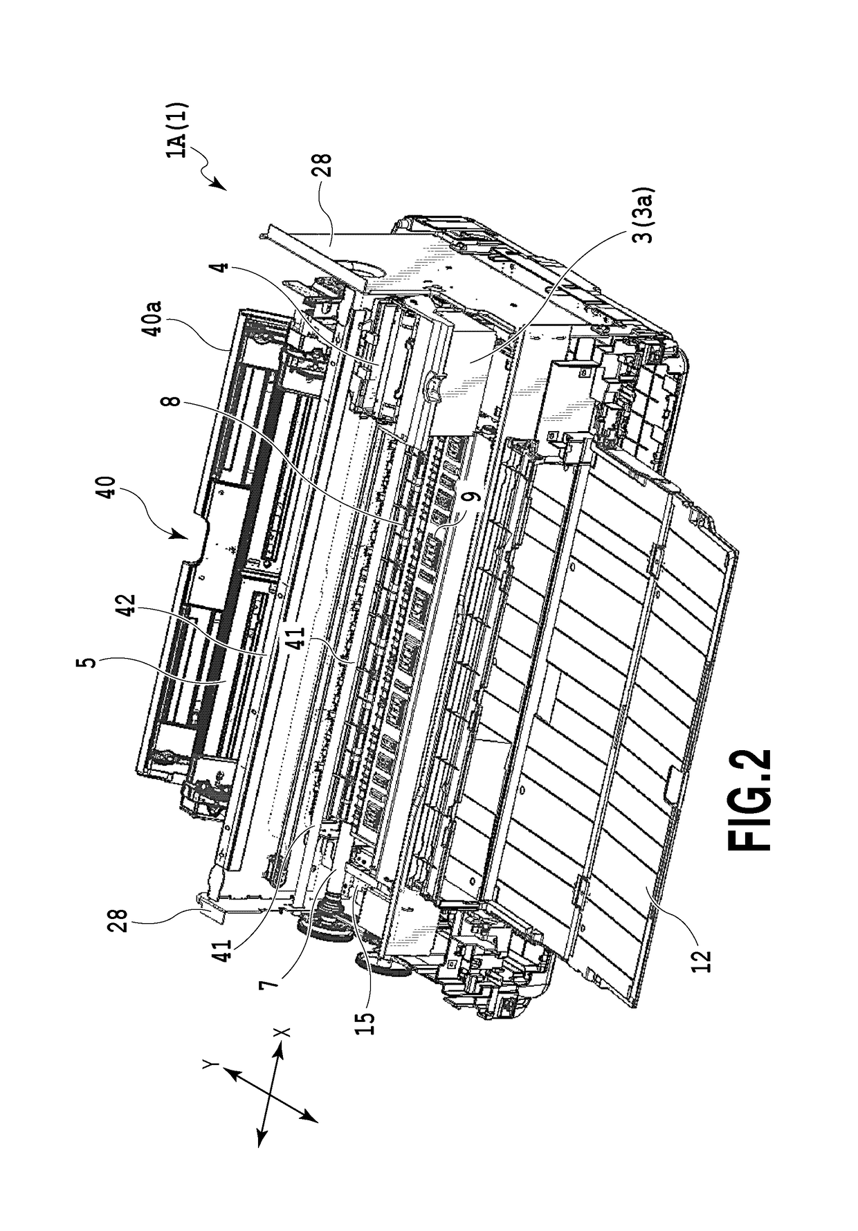
[0056]FIG. 1 is a perspective view showing the outer appearance of a printing apparatus 1 in an embodiment. At the front of the printing apparatus 1, a discharge tray 12 for supporting a printed sheet is provided, and furthermore, a console panel 1a for performing various setting operations and a display 1b are disposed. Moreover, a top cover 1c for covering the inside structure such as a carriage, described later, is openably disposed at the top of the printing apparatus 1, and furthermore, a feed tray 5 for stacking thereon sheets to be fed to a feeder 40, described later, is openably disposed at the back of the printing apparatus 1. Incidentally, although FIG. 1 shows a state in which the discharge tray 12 and the feed tray 40a are closed, both of the trays 12 and 40a can be opened during a printing operation, as shown in FIG. 2.

[0057]Here, referring to FIGS. 2 and 3, explanation will be made on the configuration of a printing apparatus body 1A. FIG. 2 is a...

second embodiment

[0116]Next, a description will be given below of a second embodiment according to the present invention. In the second embodiment, constituent elements identical or corresponding to those in the first embodiment are designated by the same reference numerals, and therefore, the explanation will be omitted.

[0117]FIGS. 22 and 23 are enlarged perspective views showing the detailed shape of a sheet supporting portion 14 in the second embodiment. Here, FIG. 22 is a perspective view partly showing a platen and a sheet, and FIG. 23 is a perspective view showing an air flow at the platen shown in FIG. 22. The sheet supporting portion 14 is obtained by forming, into a rectangular frame, a ribbed projection having a flat sheet supporting surface 13 in contact with the reverse of a sheet. A suction recess 17 (i.e., a suction unit) is formed at the upper portion of the sheet supporting portion 14, thereby forming a recess lower by one step than the sheet supporting surface 13. Suction holes 18 (...

third embodiment

Variation of Third Embodiment

[0181]Next, a variation in the third embodiment according to the present invention will be explained with reference to FIGS. 41 and 42. In the third embodiment, the step 141 is formed on the side wall 140D formed at the sheet supporting portion 14 in the vertical direction, and furthermore, the side face 142 rising from the step 141 in the substantially vertical direction is formed to define the slit for absorbing the ink between the step 141 and the side face 142. In contrast, in this variation, there are formed a first slit 423 and a second slit 424 that penetrate side walls 140A and 140D formed at the sheet supporting portion 14 in the substantially vertical direction and communicate with the negative pressure chamber 22 (see FIG. 42).

[0182]Although FIG. 41 shows cases where the first slit 423 is formed on the upstream side wall 140A whereas the second slit 424 is formed on the right side wall 140D, the first and second slits (See, for example, FIG. 4...


PUM


Abstract

A platen includes: a supporting portion that can support a sheet; a suction unit that sucks the sheet in such a manner as to attach the sheet to the supporting portion; a first ink receiver that receives ink ejected downstream of the leading end of the sheet passing the supporting portion; and a second ink receiver that receives ink ejected upstream of the trailing end of the sheet passing the supporting portion.

Description

BACKGROUND OF THE INVENTION[0001]Field of the Invention[0002]The present invention relates to an inkjet printing apparatus provided with a platen for supporting a sheet.[0003]Description of the Related Art[0004]Japanese Patent Laid-Open No. 2006-021475 discloses an ink jet printing apparatus capable of forming an image without a margin at a sheet end, that is, performing so-called “marginless printing.” The apparatus uses a suction platen that sucks a sheet by a negative pressure.[0005]According to the invention disclosed in Japanese Patent Laid-Open No. 2006-021475, in a case where marginless printing is performed at the trailing end of a sheet, the sheet is sucked to a sucking unit of a platen. In contrast, in a case where marginless printing is performed at the leading end of a sheet, the leading end of the sheet has not yet reached the sucking unit, and therefore, it has not yet sucked to the sucking unit. Thus, the floating of the leading end of the sheet cannot be suppressed a...

Claims


Application Information

Patent Timeline
Patent Type & Authority Patents(United States)
IPC IPC(8): B41J11/00B41J2/165B41J2/17B41J11/06
CPCB41J11/0085B41J2/16508B41J11/0065B41J11/06B41J2/1721B41J2002/1742B41J2/01B41J2/175B41J13/10B41J2/235B41J11/02B41J11/36B41J11/66
Inventor KURATA, TETSUJIOGASAWARA, SEIJITSUKUDA, MASAKAZUONUMA, TAKAHIDESAITO, YASUNORIMIYAKOSHI, ARIHITOKUBOTA, MASAHIKOIMAHASHI, YUSUKEYAMAGUCHI, NOBUHITOARIMIZU, HIROSHIITOH, YOSHINORI
Owner CANON KK
Why Eureka
Try Eureka