
Spindle motor

a spindle motor and spindle technology, applied in the direction of dynamo-electric machines, instruments, structural associations, etc., can solve the problems of circuit patterns formed on printed circuit boards and the top portion of the base plate coupled with the top portion of the base plate, and achieve the effect of preventing damage to the printed circuit board

Inactive Publication Date: 2012-10-18
SAMSUNG ELECTRO MECHANICS CO LTD
View PDF3 Cites 1 Cited by
  • Summary
  • Abstract
  • Description
  • Claims
  • Application Information

AI Technical Summary

Benefits of technology

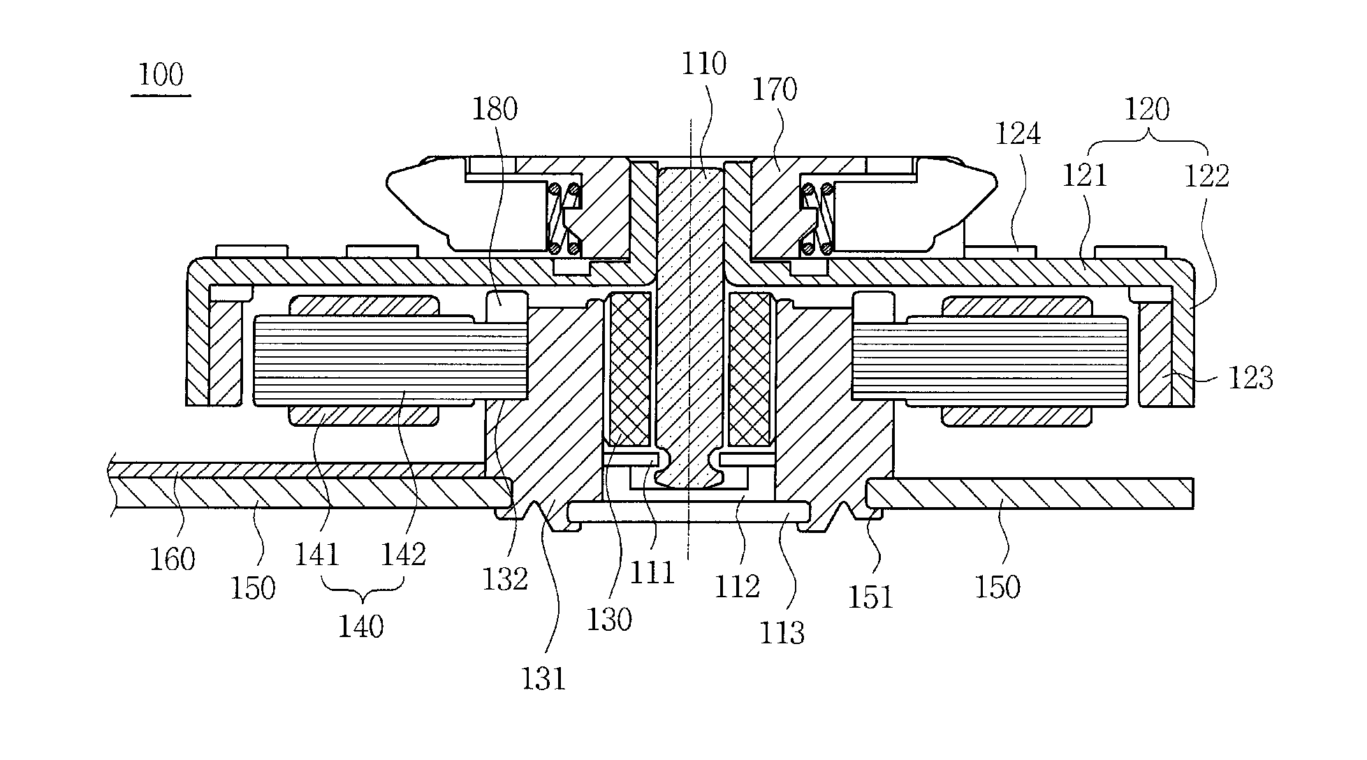
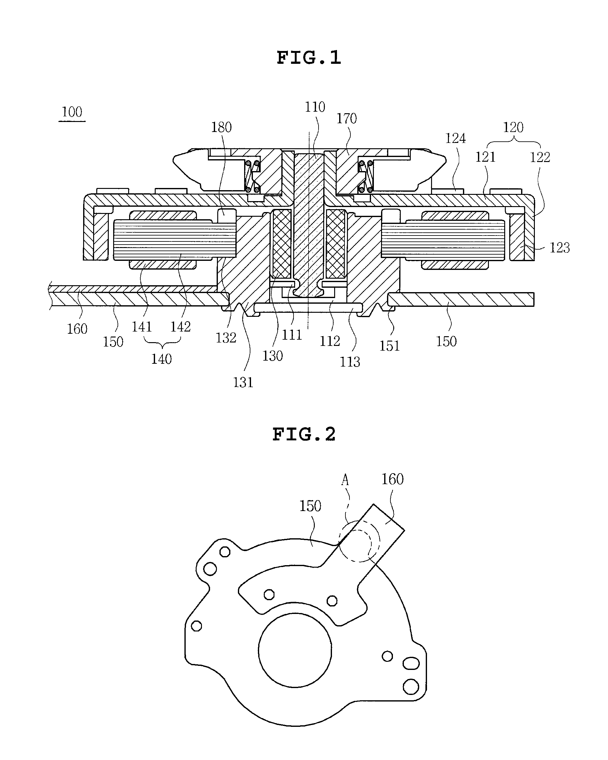
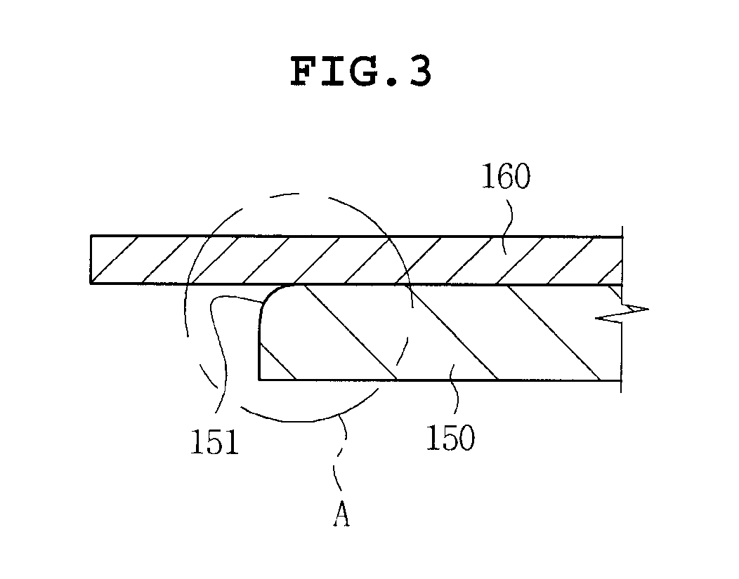
The present invention provides a spindle motor with a round shape at the end of the base plate that contacts the printed circuit board. This motor includes a rotating part and a fixing part with a printed circuit board. The rotating part rotates by the magnet and the armature, and the end of the base plate has a downward inclined part with a round shape. The printed circuit board can be a flexible printed circuit or a flexible flat cable. The rotating part includes a rotor case and a bearing holder, and the magnet is attached inside the rotor case. The bearing holder can also have a suction magnet to prevent the rotor case from floating. The printed circuit board can have circuit patterns on its top or bottom surface. The technical effects of this invention include improved motor performance and stability, reduced noise, and improved cooling efficiency.

Problems solved by technology

Therefore, the printed circuit board coupled with the top portion of the base plate and the circuit patterns formed on the printed circuit board may be damaged due to the burr formed on the base plate.

Method used


Image

  • Spindle motor
  • Spindle motor
  • Spindle motor

Examples


Embodiment Construction

[0024]The above and other objects, features and advantages of the present invention will be more clearly understood from the following detailed description taken in conjunction with the accompanying drawings. In the specification, in adding reference numerals to components throughout the drawings, it is to be noted that like reference numerals designate like components even though components are shown in different drawings. Further, when it is determined that the detailed description of the known art related to the present invention may obscure the gist of the present invention, the detailed description thereof will be omitted. In the description, the terms “first”, “second” and so on are used to distinguish one element from another element, and the elements are not defined by the above terms. The terms are only used to differentiate one component from other components. Further, when it is determined that the detailed description of the known art related to the present invention may...


PUM


Abstract

Disclosed herein is spindle motor including a rotating part, including: a rotating shaft and a magnet; a fixing part including a bearing supporting the rotating shaft, an armature opposite to the magnet, a printed circuit board applying power to the armature, and a base plate coupled with the rotating part, wherein the rotating part rotates by electromagnetic force of the magnet and the armature, and an end of the base plate contacting the printed circuit board is provided with a downward inclined part having a round shape so as to be coupled with the printed circuit board.

Description

CROSS REFERENCE TO RELATED APPLICATION[0001]This application claims the benefit of Korean Patent Application No. 10-2011-0034794, filed on Apr. 14, 2011, entitled “Spindle Motor” which is hereby incorporated by reference in its entirety into this application.BACKGROUND OF THE INVENTION[0002]1. Technical Field[0003]The present invention relates to a spindle motor.[0004]2. Description of the Related Art[0005]Generally, a spindle motor is a device that is mounted in a hard disk drive, an optical disk drive, and other recording media requiring high-speed rotation to drive a turntable so as to rotate a disk mounted in the turntable.[0006]The spindle motor according to the prior art include a chucking assembly that includes a rotating shaft, a rotor case, a bearing holder rotatably supporting the rotating shaft, an armature configured to include a coil and a core, a base plate coupled with a printed circuit board, and a turntable mounted with a disk.[0007]In detail, a magnet is provided i...

Claims


Application Information

Patent Timeline
Patent Type & Authority Applications(United States)
IPC IPC(8): H02K5/22
CPCH02K5/225G11B19/2009H02K2211/03H02K11/0068H02K11/30G11B19/20
Inventor PARK, YUN YEONGYOO, YOUNG SUNYOO, HO JUN
Owner SAMSUNG ELECTRO MECHANICS CO LTD
Learn More