Image forming apparatus

A technology for imaging equipment and extrusion components, which is applied in printing, printing devices, object supply, etc., can solve the problems of weakening the extrusion force of the nip roller device, high conveying speed of the conveyor belt, and image quality deterioration, so as to prevent image quality Deterioration, suppression of changes in conveying speed, and prevention of twisting

Inactive Publication Date: 2006-08-30
BROTHER KOGYO KK
View PDF1 Cites 1 Cited by
  • Summary
  • Abstract
  • Description
  • Claims
  • Application Information

AI Technical Summary

Problems solved by technology

Thus, the variation in the conveying speed of the conveying belt becomes large just after the recording medium has been pinched and conveyed, resulting in deterioration of image quality.
[0006] On the other hand, if the pressing force of the pinch roller device is weakened in order to suppress this change in conveying speed, floating of the recording medium occurs as described above, resulting in deterioration of image quality.

Method used


Image

  • Image forming apparatus
  • Image forming apparatus
  • Image forming apparatus

Examples


Embodiment Construction

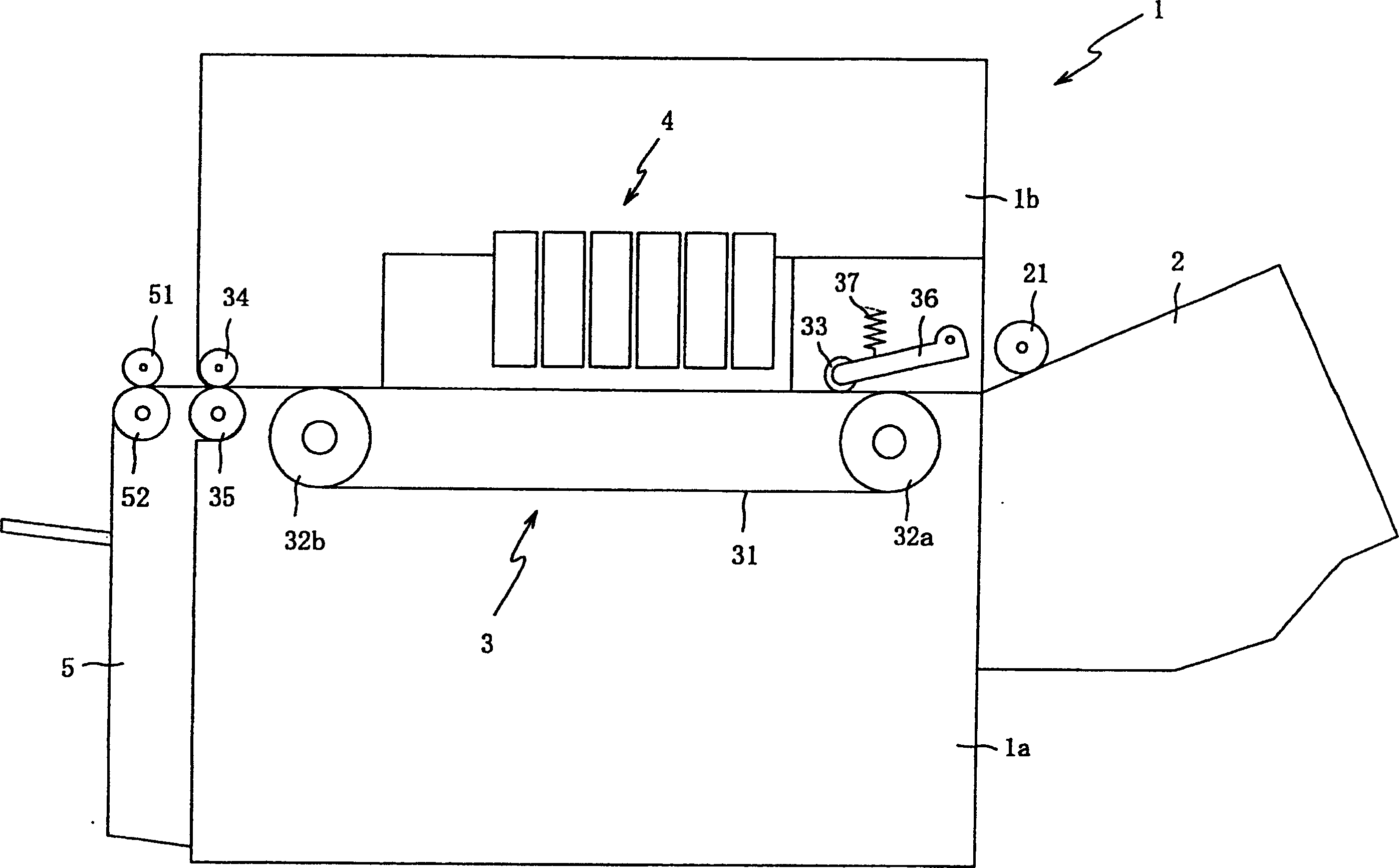
[0045] Hereinafter, preferred embodiments of the present invention will be described with reference to the accompanying drawings. figure 1 is a schematic diagram of the image forming apparatus 1 according to the first embodiment of the present invention. First refer to figure 1 The general structure of the imaging apparatus 1 is described.

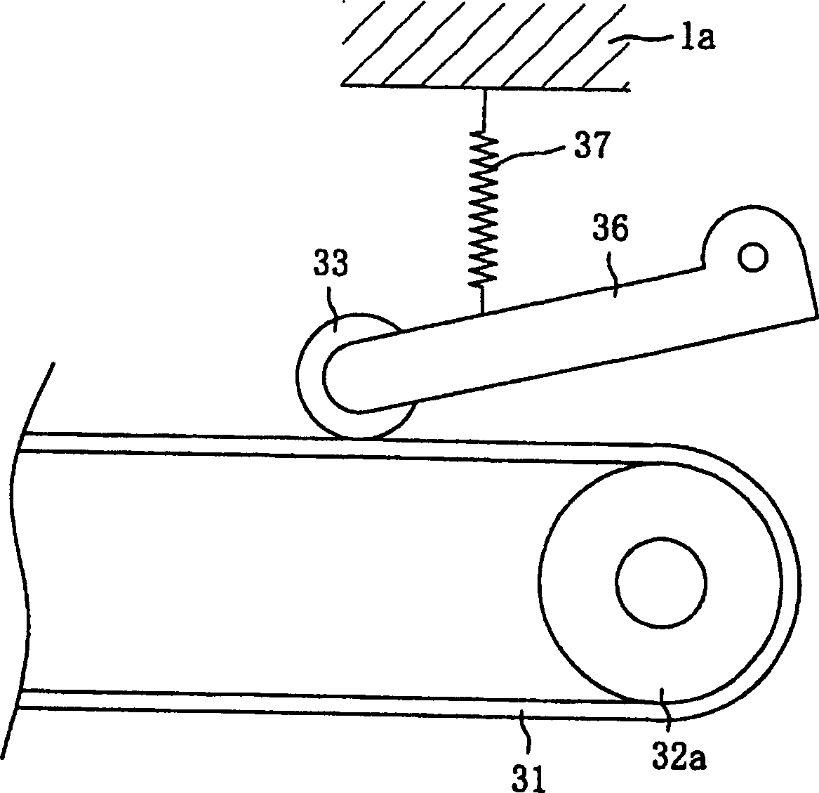
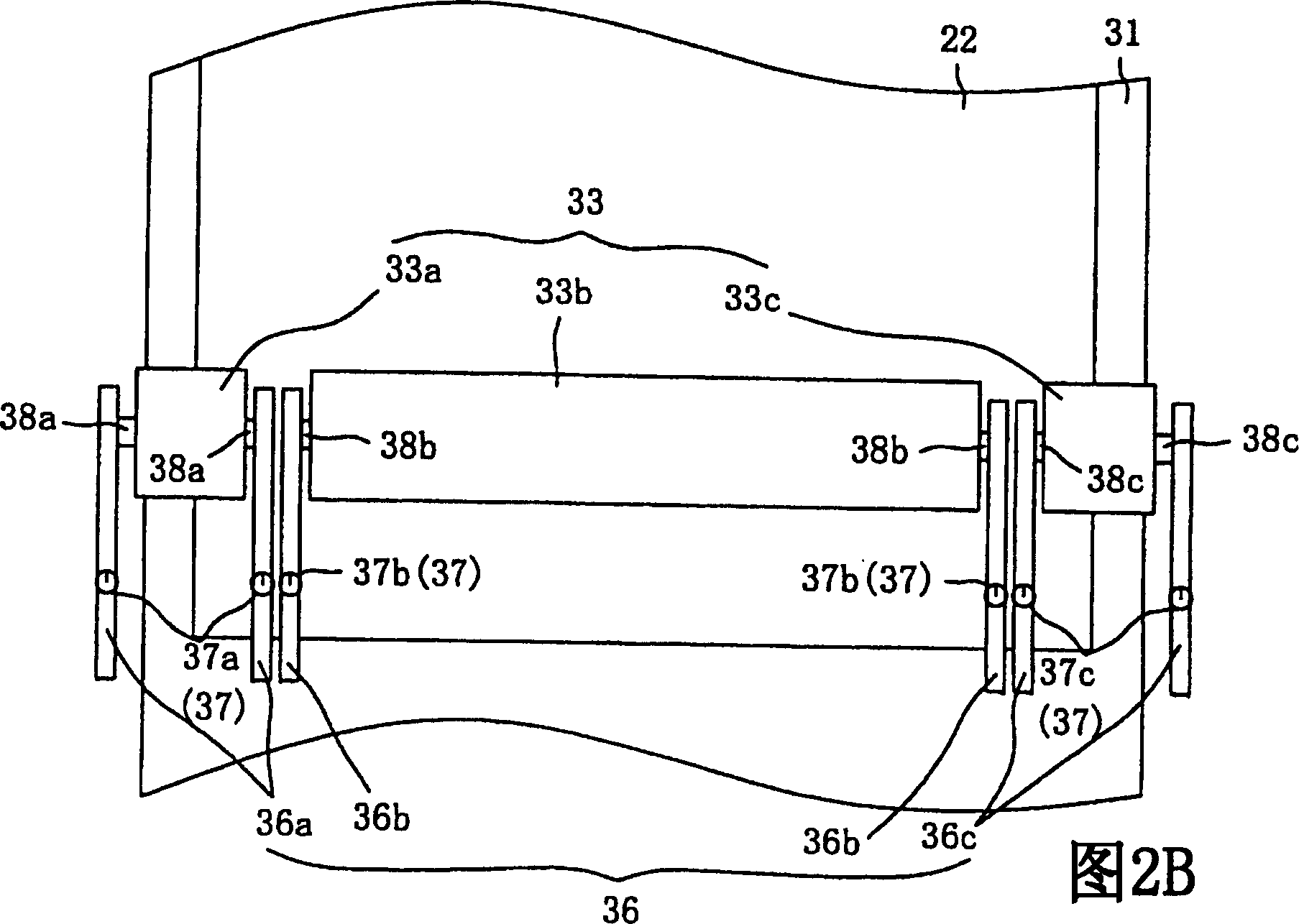
[0046] The image forming apparatus 1 mainly includes: a supply unit 2 that supplies a recording medium 22 (see FIG. 2B ) to the main body 1 a; a conveyance unit 3 that conveys the recording medium 22 supplied by the supply unit 2; , the recording head 4 ejects ink onto the recording medium 22 conveyed by the conveying unit 3 to form an image; and a stacker 5 that stores the recording medium 22 on which the image has been formed by the recording head 4 .

[0047]The supply unit 2 includes a tray (not shown) accommodating a recording medium 22 , and a pickup roller 21 that contacts the recording medium 22 accommodated in the tray. When dr...


PUM


Abstract

In an image forming apparatus (1) according to the present invention, a nip roller group (33) for pressing a face of a conveyance belt (31) on which a recording medium (22) is held includes a pair of first end pressing parts (33a, 33c) which are arranged in the width direction of the conveyance belt (31) at a distance corresponding to the recording medium (22) having a predetermined size, and a first center pressing part (33b) which is arranged between the pair of first end pressing parts (33a, 33c). Herein, a pressing force of the first center pressing part (33b) is set to be smaller than pressing forces of the first end pressing parts (33a, 33c).

Description

technical field [0001] The present invention relates to an imaging device. In particular, the present invention relates to an image forming apparatus that suppresses variations in conveying speed of a conveying belt and floating of a recording medium to prevent image quality from deteriorating. Background technique [0002] In an image forming apparatus that forms a desired image on a recording medium held on an endless conveyor belt, the recording medium held on the conveyor belt generally tends to float. Such floating makes it difficult to maintain the recording medium in a horizontal state with respect to the recording head for ink ejection, resulting in deterioration of image quality. [0003] In order to solve this problem, Japanese Laid-Open Patent Application No. 2-86475 (1990) discloses a technique of disposing cylindrical nip rollers (pinch roller means) on the conveying surface of a belt (conveyor belt). According to this technique, the pinch rollers press the re...

Claims


Application Information

Patent Timeline
Patent Type & Authority Applications(China)
IPC IPC(8): B41J11/02B41J2/01B41J13/00B65H5/02
CPCB41J13/076B41J11/007
Inventor 中岛笃久
Owner BROTHER KOGYO KK
Why Eureka
Try Eureka