Instrument systems and methods utilizing optical fiber sensor

a technology of optical fiber and instrument system, applied in the field of robot controlled systems, can solve the problems of affecting the operation, affecting the operation, and requiring long recovery time, and achieve the effect of preventing the twisting of the fiber

Active Publication Date: 2013-04-11
KONINKLIJKE PHILIPS ELECTRONICS NV
View PDF7 Cites 113 Cited by
  • Summary
  • Abstract
  • Description
  • Claims
  • Application Information

AI Technical Summary

Benefits of technology

[0052]According to yet another embodiment of the present disclosure, an instrument system that includes an elongate instrument body and an optical fiber is provided. The optical fiber is coupled to the elongate instrument body, wherein at least one of the optical fiber and the elongate instrument body has a structural attribute that prevents twisting of the optical fiber relative to the elongate instrument body.

Problems solved by technology

Traditionally, surgery utilizing conventional procedures meant significant pain, long recovery times, lengthy work absences, and visible scarring.
Without a traditional large and invasive incision, the surgeon is not able to see directly into the patient.
MIS procedures may involve minor surgery as well as more complex operations.
In known robotic instrument systems, however, the ability to control and manipulate system components such as catheters and associated working instruments may be limited due, in part, to a surgeon not having direct access to the target site and not being able to directly handle or control the working instrument at the target site.
However, controlling one or more catheters that are advanced through naturally-occurring pathways such as blood vessels or other lumens via surgically-created wounds of minimal size, or both, can be a difficult task.
Remotely controlling distal portions of one or more catheters to precisely position system components to treat tissue that may lie deep within a patient, e.g., the left atrium of the heart, can also be difficult.
These difficulties are due in part to limited control of movement and articulation of system components, associated limitations on imaging and diagnosis of target tissue, and limited abilities and difficulties of accurately determining the shape and / or position of system components and distal portions thereof within the patient.
These limitations can complicate or limit the effectiveness of surgical procedures performed using minimally invasive robotic instrument systems.
A drawback of known fluoroscopic imaging systems is that it they are projection based such that depth information is lost.
As a result, true three-dimensional location of objects such as an elongate instrument in the field of view of the fluoroscope is lost as a result of generating a two-dimensional fluoroscopic image.
Thus, even if it is possible to obtain accurate x-y or two-dimensional data, it may be difficult or impossible to accurately determine the location of a catheter in three-dimensional space.
In the example illustrated in FIG. 1, the shapes of the representation 12 and image 14 are generally consistent, but in some applications, the position and / or shape of a catheter or elongate instrument may differ and inaccurately reflect the shape and / or position of the instrument, which may result in complications during surgical procedures.
Such mismatches may be interpreted as a problem associated with the kinematics model or controls or sensing algorithms, or as a result of contact between the subject instrument and a nearby object, such as tissue or another instrument.
This process, however, can be tedious, and it is relatively easy for the elongate instrument to go out of alignment relative to the other pertinent coordinate systems.

Method used


Image

  • Instrument systems and methods utilizing optical fiber sensor
  • Instrument systems and methods utilizing optical fiber sensor
  • Instrument systems and methods utilizing optical fiber sensor

Examples


Embodiment Construction

[0054]Embodiments of the invention are related to systems, apparatus and methods including or involving the use of optical fiber sensors, e.g., Fiber-Bragg sensors, which may be used to provide accurate shape and / or position data of an elongate instrument.

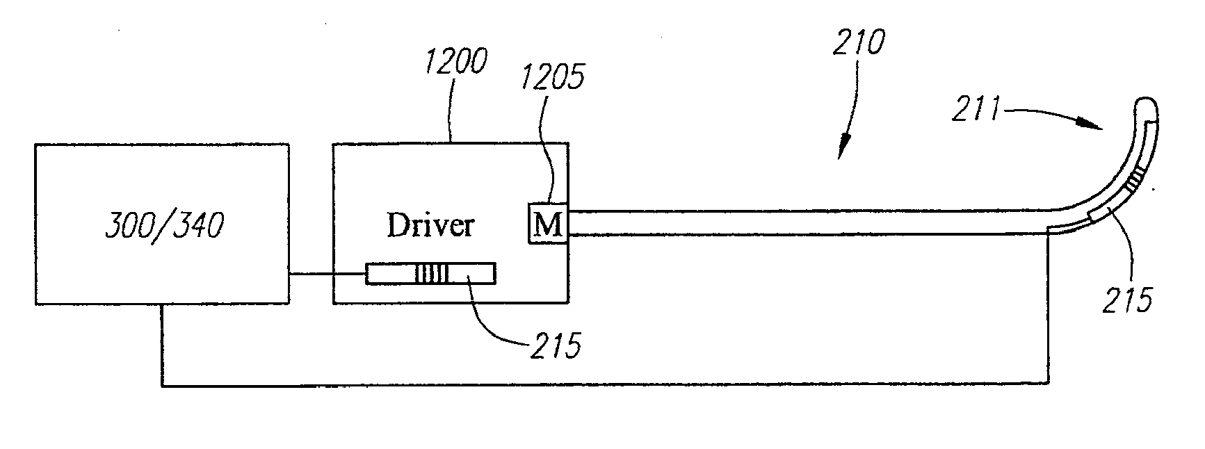
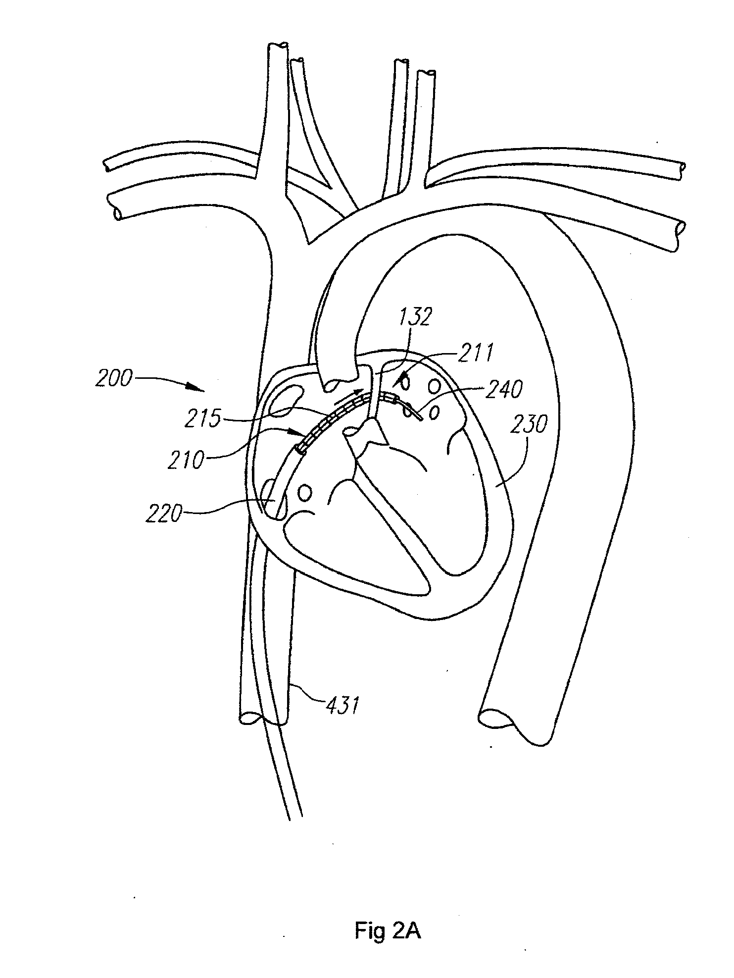
[0055]Referring to FIG. 2A, according to one embodiment, one or more components of a robotically controlled instrument 200 of a robotic surgical system include an optical fiber or fiber sensor 215 (referred to as optical fiber sensor or fiber 215), which is coupled to, or an integral part of, an elongate instrument body 210. Data based on light reflected by gratings of the fiber 215 may be used to determine the shape and / or position of the elongate instrument, which may be a catheter, such as a guide catheter. In the illustrated embodiment, the elongate instrument or catheter 210 is a part of a robotically controlled instrument 200 that it utilized to position a bendable distal end portion 211 of the catheter 210 and one or more wo...


PUM


Abstract

An instrument system that includes an elongate instrument body and an optical fiber sensor is provided. The optical fiber sensor includes an elongate optical fiber that is coupled to the elongate instrument body, wherein a portion of the optical fiber is coupled to the elongate instrument body in a manner to provide slack in the fiber to allow for axial extension of the elongate instrument body relative to the optical fiber.

Description

CROSS-REFERENCE TO RELATED APPLICATION[0001]The present application is a divisional of U.S. patent application Ser. No. 12 / 192,033 filed on Aug. 14, 2008, which claims the benefit under 35 U.S.C. §119 to U.S. Provisional Application No. 60 / 964,773, filed on Aug. 14, 2007, the contents of which is incorporated herein by reference as though set forth in full.[0002]The present application may also be related to subject matter disclosed in the following applications, the contents of which are also incorporated herein by reference as though set forth in full: U.S. patent application Ser. No. 10 / 923,660, entitled “System and Method for 3-D Imaging”, filed Aug. 20, 2004; U.S. patent application Ser. No. 10 / 949,032, entitled “Balloon Visualization for Transversing a Tissue Wall”, filed Sep. 24, 2005; U.S. patent application Ser. No. 11 / 073,363, entitled “Robotic Catheter System”, filed Mar. 4, 2005; U.S. patent application Ser. No. 11 / 173,812, entitled “Support Assembly for Robotic Catheter...

Claims


Application Information

Patent Timeline
Patent Type & Authority Applications(United States)
IPC IPC(8): A61B1/00
CPCA61B5/06A61B8/00A61B6/12A61B19/2203A61B19/5244A61B19/54A61B2019/2211A61B2019/2223A61B2019/2242A61B2019/2246A61B2019/2273A61B2019/2296A61B2019/442A61B2019/448A61B2019/5236A61B2019/5238A61B2019/5261A61B2019/5276G01B11/16G01B11/165A61B1/00013A61B1/0017A61B1/00057G01L1/242A61B1/00004A61B5/4887A61B8/48A61B5/0064A61B18/082A61B1/00045A61B1/00165A61B5/0059A61B5/7285A61B2034/715A61B90/96A61B34/20A61B34/71A61B2034/301A61B2090/376A61B34/30A61B34/37A61B2034/741A61B34/77A61B90/98A61B2090/374A61B2034/2061A61B2090/378A61B90/39A61B2017/00725A61B5/065A61B5/066A61B2017/00699A61B18/1492A61B1/009A61B18/22A61M2025/0166
Inventor RAMAMURTHY, BHASKAR S.TANNER, NEAL A.YOUNGE, ROBERT G.SCHLESINGER, RANDALL L.
Owner KONINKLIJKE PHILIPS ELECTRONICS NV
Why Eureka
Try Eureka