Stapler beam architecture

a beam and beam technology, applied in the field of surgical devices, can solve problems such as the reduction of the efficiency of force transmission, and achieve the effect of adequate axial stiffness and reduced bending stiffness of tubes

Active Publication Date: 2021-11-09
INTUITIVE SURGICAL OPERATIONS INC
View PDF27 Cites 132 Cited by
  • Summary
  • Abstract
  • Description
  • Claims
  • Application Information

AI Technical Summary

Benefits of technology

[0005]In many embodiments, a flexible actuation assembly that extends through a wrist that can yaw and / or pitch at relatively large angles includes a pulling assembly and a pushing assembly. The flexible actuation assembly can be used to open and close jaws of a surgical device and / or to actuate other implements such as cutting and / or stapling devices. In many embodiments, the pushing element can transmit compressive force even while having a substantial amount of curvature induced via high yaw and / or pitch angles of the wrist. In many embodiments, the pushing assembly does not transmit significant amount of tensile force and the pulling element is used to transmit tensile force for proximal movement and actuation of the surgical device. In a similar manner, the pulling component may not transmit significant amount of compressive force. In many embodiments, the combination of the pushing assembly and the pulling assembly into the flexible actuation assembly enables use of the flexible actuation assembly for both compressive and tensile force application (i.e.,) pushing and pulling) to actuate components of an end effector of a surgical device.
[0007]To enable a high degree of wrist flexibility, the wrist assembly can be constructed from outer links that define yaw and pitch geometry for the wrist assembly. The outer links can house a flexible portion of the actuation mechanism. However, compression of the actuation mechanism within a wrist can cause buckling and decrease efficiency of force transmission. To help mitigate such issues, inner links can be provided that connect the outer links to one another. The inner links can define a passage that constrains and limits lateral movement of the actuation mechanism, and thus mitigate buckling.
[0010]The pushing assembly of the apparatus can have any suitable configuration. For example, the pushing assembly can include an inner lumen that surrounds the pulling assembly. The pushing assembly can include a close-coiled spring. The close-coiled spring can have a cylindrical outer surface. The close-coiled spring can have interfacing convex and concave surfaces. The close-coiled spring can include a spiral cut tube. The pushing assembly can include a tube having a pattern of recesses that reduce bending stiffness of the tube while maintaining adequate axial stiffness to transmit compressive force to the beam member. The pushing assembly can include a plurality of pushing elements that separate under tension. The pushing assembly can include a plurality of spherical members. The pulling assembly can define an inner lumen that houses the plurality of spherical members. The spherical members can be linked by a flexible rod. The pushing assembly can include a plurality of separate elements having interfacing surfaces that limit transverse relative sliding between the elements to one direction. The pushing assembly can include a plurality of separate elements having interfacing surfaces that inhibit relative twisting between the elements. The pushing assembly can include a stack of flat washers. The pushing assembly can include a stack of torus disks. The pushing assembly can include a stack of rectangular washers defining a lumen through which the plurality of sheet metal bands extends. The bending stiffness of the pushing assembly can be the same for actuation of the wrist that pitches the end effector relative to the elongated shaft and actuation of the wrist that yaws the end effector relative to the elongated shaft.

Problems solved by technology

However, compression of the actuation mechanism within a wrist can cause buckling and decrease efficiency of force transmission.

Method used


Image

  • Stapler beam architecture
  • Stapler beam architecture
  • Stapler beam architecture

Examples


Embodiment Construction

[0040]In the following description, various embodiments will be described. For purposes of explanation, specific configurations and details are set forth in order to provide a thorough understanding of the embodiments. However, it will also be apparent to one skilled in the art that the embodiments may be practiced without the specific details. Furthermore, well-known features may be omitted or simplified in order not to obscure the embodiment being described.

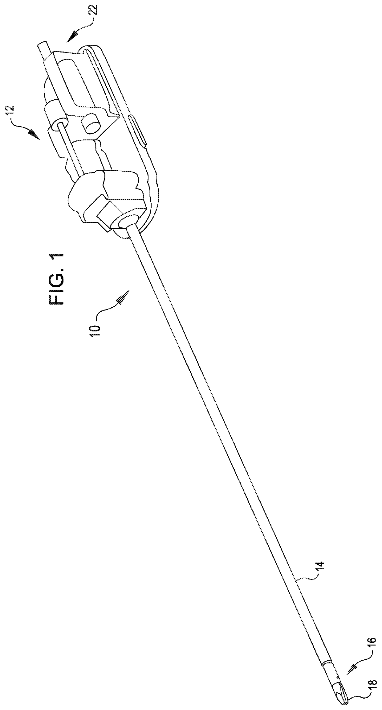
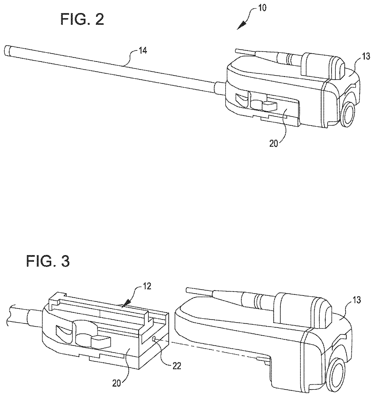
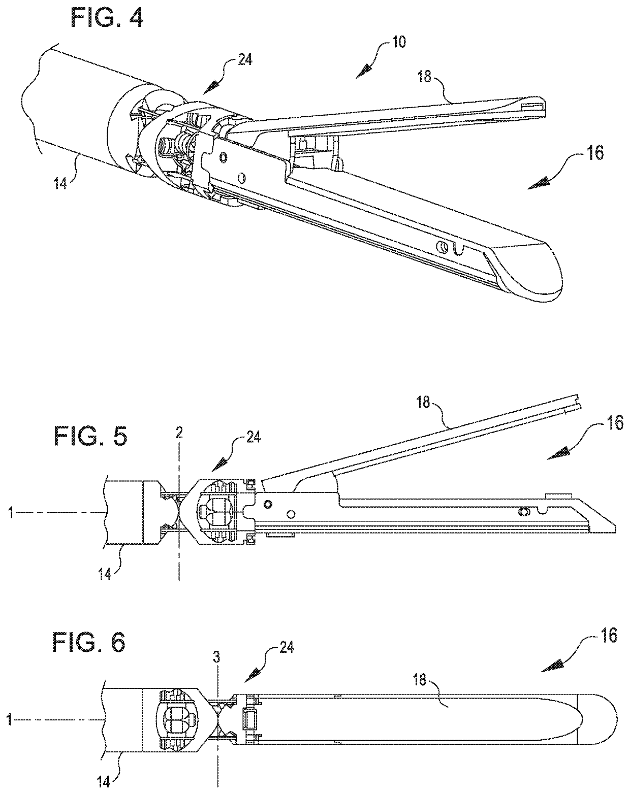
[0041]FIGS. 1-3 show a surgical tool 10 that includes a proximal chassis 12, an instrument shaft 14, and a distal end effector 16 having an upper jaw 18 that can be articulated to grip a patient tissue. The proximal chassis 12 includes input couplers 22 that may interface with and be driven by corresponding output couplers of a telesurgical surgery system, such as the system disclosed within Pub. No. US 2014 / 01.83244 Al, which is incorporated by reference herein. The input couplers 22 are drivingly coupled with one or more inpu...


PUM


Abstract

An end effector that can have an upper jaw and a lower jaw. A wrist can connect the end effector to an elongated shaft. A beam member can be arranged to translate within the upper and lower jaw. An actuation assembly can have a pushing assembly configured to transfer compressive force to the beam member and a pulling assembly configured to transfer tensile force to the beam member.

Description

CROSS REFERENCE TO RELATED APPLICATION DATA[0001]The present application is a U.S. National Stage Application of PCT / US2017 / 050735 filed Sep. 8, 2017; which claims the benefit of U.S. Provisional Appln. No. 62 / 385,636 filed Sep. 9, 2016; the full disclosures which are incorporated herein by reference in their entirety for all purposes.BACKGROUND[0002]Minimally invasive surgical techniques are aimed at reducing the amount of extraneous tissue that is damaged during diagnostic or surgical procedures, thereby reducing patient recovery time, discomfort, and deleterious side effects. As a consequence, the average length of a hospital stay for standard surgery may be shortened significantly using minimally invasive surgical techniques. Also, patient recovery times, patient discomfort, surgical side effects, and time away from work may also be reduced with minimally invasive surgery.[0003]A common form of minimally invasive surgery is endoscopy, and a common form of endoscopy is laparoscop...

Claims


Application Information

Patent Timeline
Patent Type & Authority Patents(United States)
IPC IPC(8): A61B34/35A61B17/072A61B17/00A61B17/29A61B34/30
CPCA61B34/35A61B17/07207A61B2017/00309A61B2017/00367A61B2017/00477A61B2017/00867A61B2017/07271A61B2017/07278A61B2017/07285A61B2017/2902A61B2017/2927A61B2034/305A61B34/30
Inventor RAGOSTA, NICHOLASWIXEY, MATTHEW A.
Owner INTUITIVE SURGICAL OPERATIONS INC
Why Eureka
Try Eureka