Droplet extraction from a liquid column for on-chip microfluidics

a microfluidic and liquid column technology, applied in the field of microfluidics, can solve the problems of difficult to achieve the subsequent transport of the band to these secondary evaluation stations, and achieve the effect of effectively draining a portion of the microfluidic system, preventing distortion, and preventing the draining of any portion

Inactive Publication Date: 2012-11-06
ADVANCED LIQUID LOGIC
View PDF5 Cites 122 Cited by
  • Summary
  • Abstract
  • Description
  • Claims
  • Application Information

AI Technical Summary

Benefits of technology

[0009]At the extraction point means are provided on one side of the column or channel to extract a segment of fluid from the channel or column. This is accomplished by providing an EWOD surface or other microfluidic technology for driving droplets adjacent the extraction point. Generally, the extraction point also includes an opening in the channel or column wall opposite the extraction means. This opening is equipped with an EWOD surface or other means to transport a refill droplet to the opening opposite the extraction means. When the extraction means attempts to pull a volume of fluid from the column or channel, the cohesive nature of water molecules resists this force and exerts an opposite “pull back” force. If the droplet is nevertheless extracted, the other bands of separated particles or molecules within the column or channel become mixed or distorted. Further, part or all of the contents of the channel or column may follow the extracted droplet effectively draining a portion of the microfluidic system. The refill droplet obviates this problem by neutralizing the “pull back” force and stabilizing the fluid stream within the column or channel. As the extraction means pulls the droplet out one side of the column or channel, the refill droplet is moved into the channel or column to occupy the area previously occupied by the extracted droplet. This prevents distortion or mixing of the bands of particles or molecules within the column or channel and prevents the draining of any portion of the fluidic system.

Problems solved by technology

However, these secondary instruments are often not co-located with or in close proximity to the primary analytical device; rather they may be located downstream or external to the channel-structure and thus require the transport or transfer of the concentrated band from the primary analytical device to such secondary locations.
The subsequent transport of the band to these secondary evaluation stations is difficult to achieve without disturbing the column of fluid in the primary channel thereby incurring unwanted diffusion or pressure-driven dispersion of the concentrated molecules or particles.

Method used


Image

  • Droplet extraction from a liquid column for on-chip microfluidics
  • Droplet extraction from a liquid column for on-chip microfluidics
  • Droplet extraction from a liquid column for on-chip microfluidics

Examples


Embodiment Construction

[0014]The following description is provided to enable any person skilled in the art to make and use the invention and sets forth the best modes contemplated by the inventor of carrying out his invention. Various modifications, however, will remain readily apparent to those skilled in the art, since the general principles of the present invention have been defined herein specifically to provide a method of extracting a single droplet from a separation column or channel in a microfluidic device.

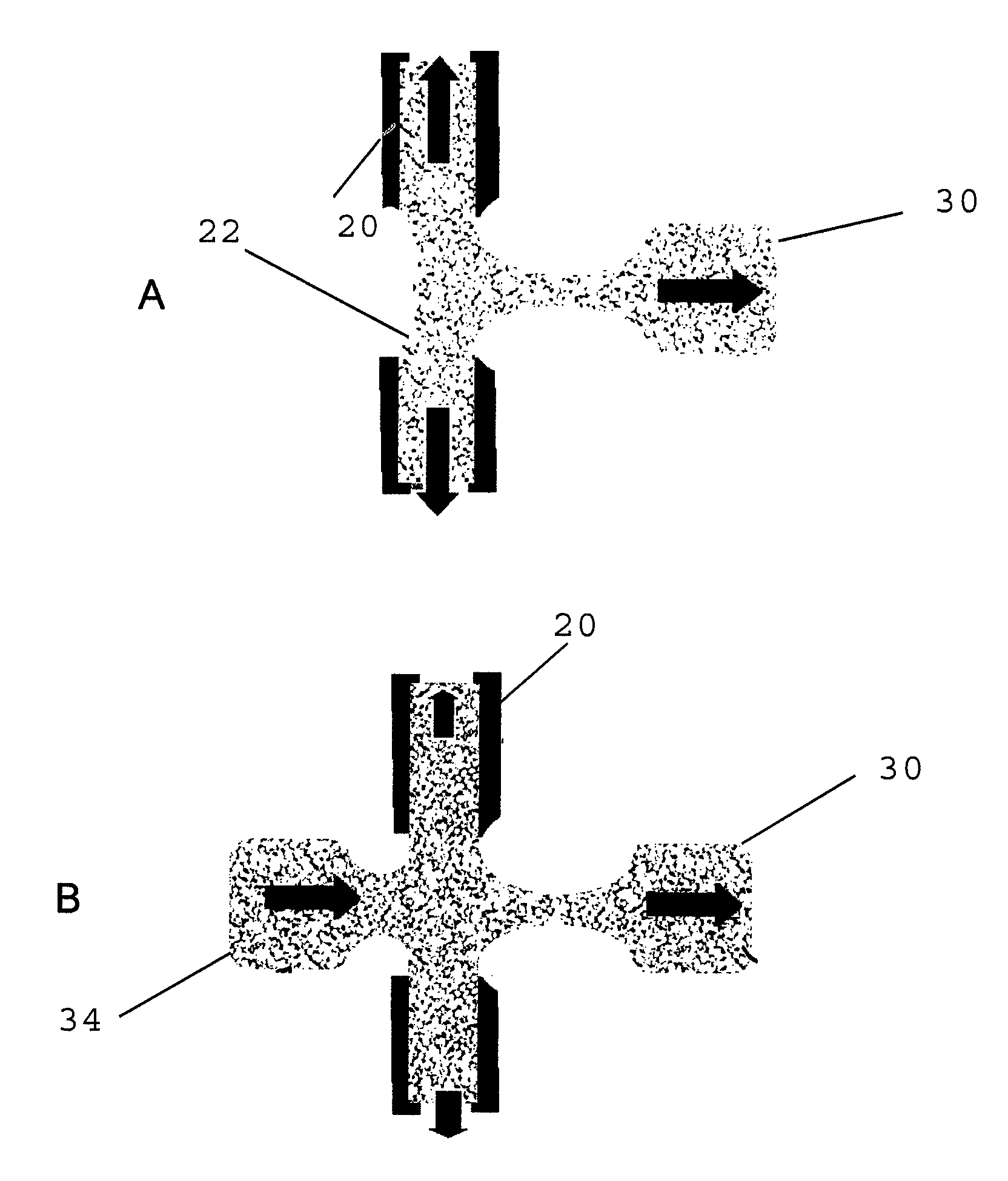
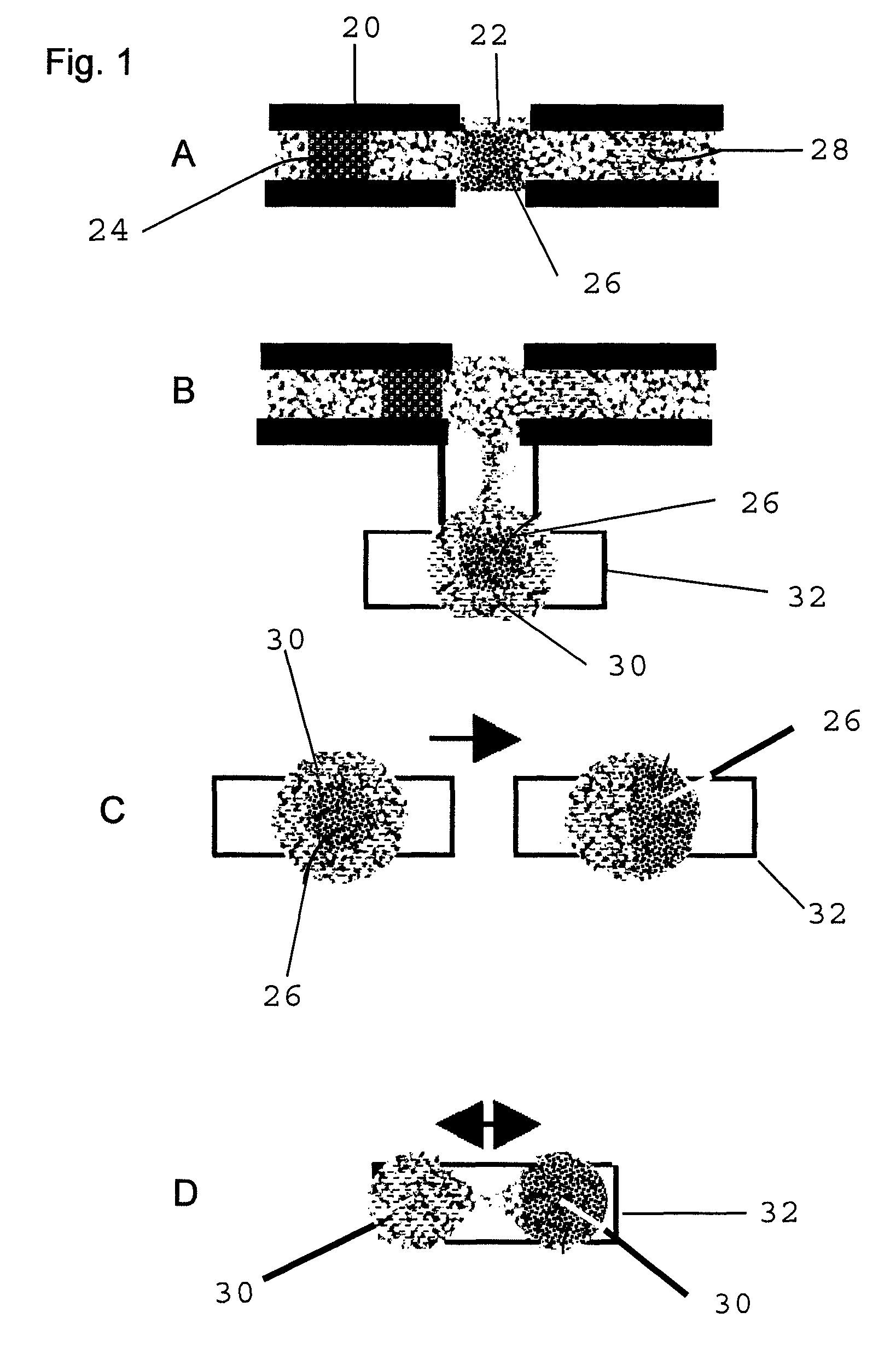
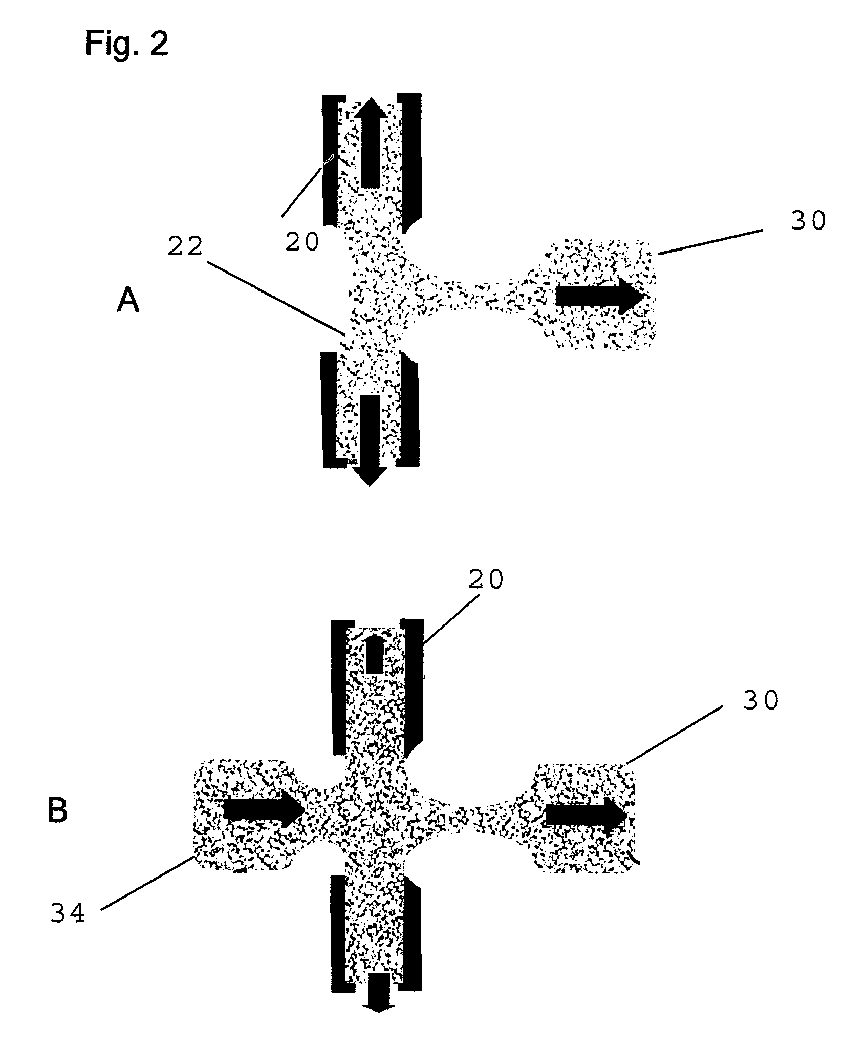
[0015]The present invention solves this problem by integrating liquid column-based transport and separation functions with Digital Microfluidic droplet handling to extract a mobile droplet that has been enriched with column-concentrated solute molecules. Extraction of a solute-rich droplet enables additional follow-on operations to be applied to the enriched sample volume, such as further in-droplet sample purifications (see e.g., “Particle Separation and Concentration Control for Digital Micro...


PUM

PropertyMeasurementUnit
lengthaaaaaaaaaa
heightaaaaaaaaaa
heightaaaaaaaaaa

Abstract

A refill droplet facilitates the extraction of a droplet laterally from a channel in a microfluidic apparatus. Such extraction allows a discrete band of separated particles or solute molecules to be excised from a fluid stream and processed and analyzed separately. An extraction point is located along the length of the channel and includes an EWOD surface or similar microfluidic technology to extract a droplet. An opening in the channel opposite the extraction means is equipped with microfluidic technology to transport a refill droplet to the opening. The refill droplet is moved into the channel or column to occupy the area previously occupied by the extracted droplet. This prevents distortion or mixing of the bands of particles or molecules within the channel and prevents the draining of any portion of the fluidic system.

Description

CROSS-REFERENCE TO PRIOR APPLICATIONS[0001]The present application is the non-provisional version of U.S. Provisional Patent Application 60 / 728,985, filed on 22 Oct. 2005, and claims the benefit and priority of that application.GRANT INFORMATION[0002]This invention was made with government support under NBCHC-05-0123 and NBCHC-06-0082 awarded by Department of Homeland Security Advanced Research Projects Agency (HSARPA). The government has certain rights in the invention.BACKGROUND OF THE INVENTION[0003]1. Area of the Art[0004]The present invention concerns the art of microfluidics—namely the transport and processing of fluid samples on a micro-scale.[0005]2. Description of the Background Art[0006]This invention addresses the problem of extracting sample droplets from liquid columns by means of surface phenomena, particularly by means of electrowetting, to enable multi-staged separation and analysis functions external to the original microfluidic circuit. Digital Microfluidics (see, ...

Claims


Application Information

Patent Timeline
Patent Type & Authority Patents(United States)
IPC IPC(8): B01D57/00B01L99/00
CPCB01L3/502B01L3/502792B01L3/502761B01L2200/027B01L2200/10B01L2300/0816Y10T436/25375B01L2300/161B01L2400/0427B01L2400/0469G01N1/10Y10T436/2575Y10T436/25B01L2300/089
Inventor YI, UICHONG BRANDONDE GUZMAN, PETER PATRICKLIU, WAYNEKIM, CHANG-JIN
Owner ADVANCED LIQUID LOGIC
Why Eureka
Try Eureka