Pneumatic tire and tire wheel assembly

a pneumatic tire and tire wheel technology, which is applied in the direction of inflatable tyres, vehicle components, non-skid devices, etc., can solve the problems of premature wear of the tread at increased reaction force, and violent wear of the tread in the axially inner side portion, so as to reduce the reaction force, and enhance the silentness of the vehicle interior

Inactive Publication Date: 2005-11-24
BRIDGESTONE CORP
View PDF13 Cites 19 Cited by
  • Summary
  • Abstract
  • Description
  • Claims
  • Application Information

AI Technical Summary

Benefits of technology

[0097] As a result of main studies on solid propagation sound for the purpose of enhancing the silentness in the vehicle interior, it is clear that vibrations of the wheel largely exerts on the solid propagation sound, which has hitherto been considered to be mainly elastic vibrations of the tire consisting of an elastomer such as rubber or the like.
[0098] As to the tire vibrations transmitted from the tread portion of the tire through a pair of sidewall portions, a pair of bead portions and the wheel toward the vehicle body, as the transmission ratio from each sidewall portion to the wheel is examined, there is frequently caused a difference between the transmission ratio through the rim end located at the front side of the wheel disc and the vibration transmission ratio through the rim end located at the rear side of the wheel disc, and it has been confirmed that which side of easily causing wheel shaft vibrations is determined by the connecting position between the rim and the disc in the wheel irrespectively of an offset amount

Problems solved by technology

In the tire having a tread pattern of such a construction, however, when a negative camber is particularly applied to the tire in use, there are problems that the wearing of the tread in the axially inner side portion becomes violent and also

Method used


Image

  • Pneumatic tire and tire wheel assembly
  • Pneumatic tire and tire wheel assembly
  • Pneumatic tire and tire wheel assembly

Examples


example 1

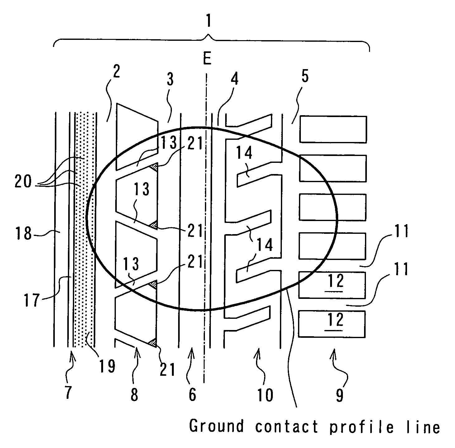
[0188] Each of example tires and comparative example tires having a tire size of 225 / 55 R16 is assembled onto a rim of 7.0J-16 and filled under an air pressure of 210 kPa and mounted onto a vehicle. The vehicle is actually run at a state of two crewmen riding under a condition that a negative camber of a front wheel is 0.3° and a negative camber of a rear wheel is 0.5°, during which a wear ratio of shoulder land part rows, a speed generating a hydroplaning phenomenon, a vehicle interior noise and a steering stability on a dry road surface are measured.

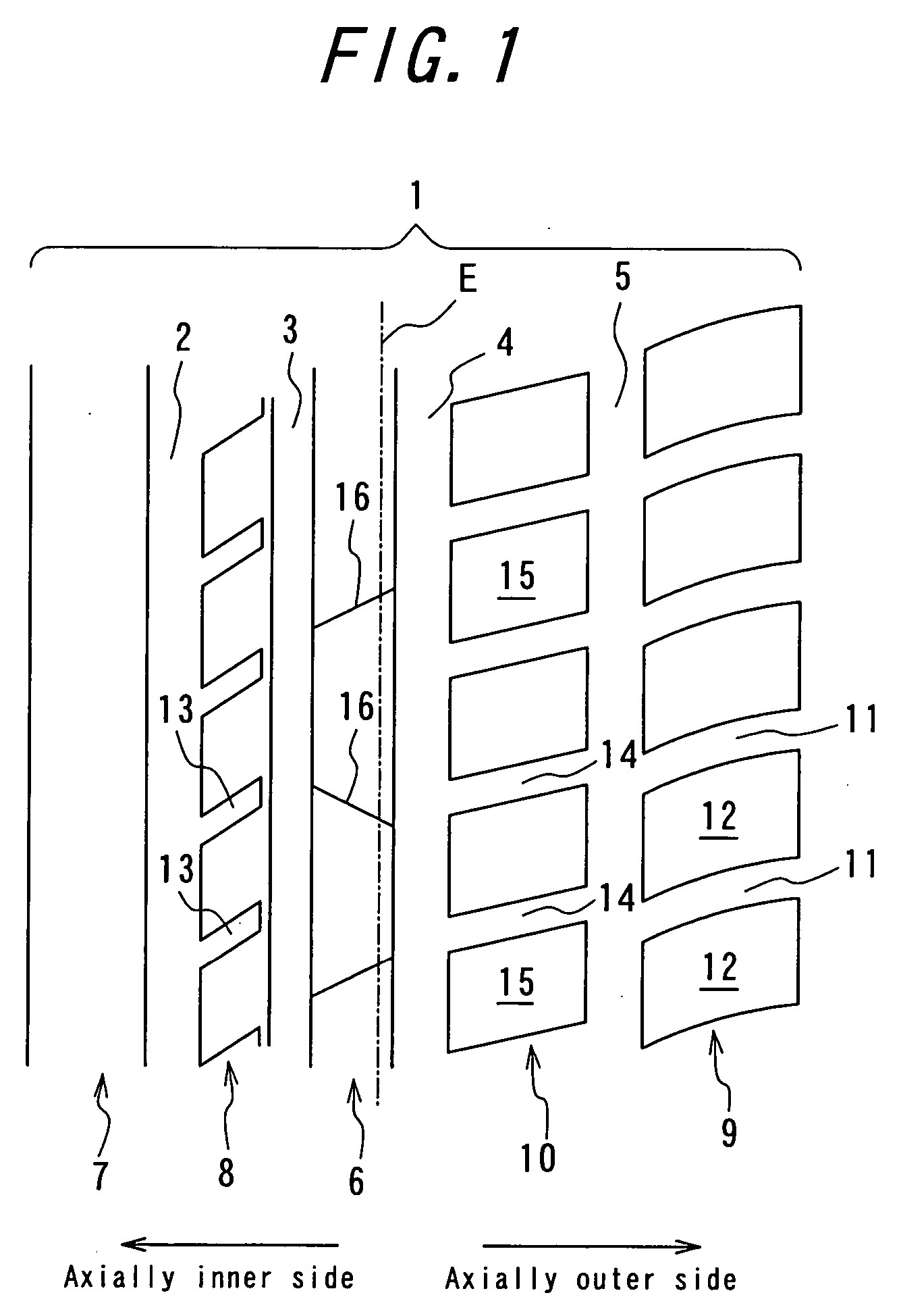
[0189] Example tire 1 has a tread pattern shown in FIG. 1, in which a slant groove in a second inner land part row has an angle of 45° with respect to a widthwise direction of a tread and an extending angle of a lateral groove in a second outer land part row is 30° and an average extending angle of a lateral groove in a shoulder land part row of an axially outer side is 15°.

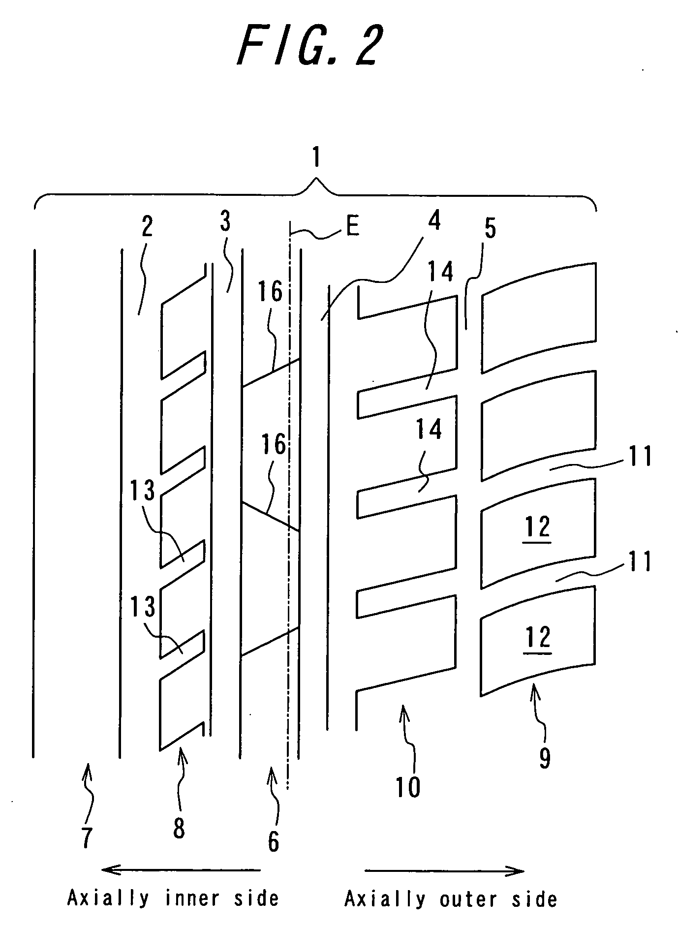
[0190] Example tire 2 has a tread pattern shown in FIG. 2, i...

example 2

[0206] Each of example tires and comparative example tires having a tire size of 215 / 45 R17 and a tread pattern shown in FIG. 25 is assembled onto a rim of 7.5J×17 and filled with an internal pressure of 220 kPa, and a camber angle of −0.5° is applied to make a ground contact length of an axially inner side long, and thereafter a slip angle is changed from 0 degree to 5 degrees at a speed of 30 km / h to measure a cornering force generated.

[0207] When a difference of cornering force between 0 degree and 1 degree is Cf1 and a difference of cornering force between 0 degree and 2.5 degrees is Cf2 and a difference between 0 degree and 5 degrees is Cf3, if Cf2 / Cf1 is 2.5 and Cf3 / Cf1 is 5, the cornering force is linearly generated, while if Cf2 / Cf1 is larger than 2.5, the cornering force increases non-linearly at a position having a large slip angle, and if Cf2 / Cf1 is smaller than 3, the cornering force decreases non-linearly.

[0208] In these tires, an integral value of rigidities of the l...

example 3

[0212] Each of example tires and comparative example tires having a tire size of 235 / 45 R17 is assembled onto a rim of 8J×17 under an internal pressure of 210 kPa and mounted onto a vehicle in which a camber angle at a front wheel is −0.4° and that at a rear wheel is −0.6° at a state of two crewmen riding.

[0213] This vehicle is subjected to a wearing test. The test condition is that it is run on an expressway, a general purpose road and a mountain path at a ratio of 50%, 40% and 10% over 20000 km. After the running, a ratio of worn amounts of widthwise central portions of both shoulder land part rows in two front wheels is measured. A case that the ratio is larger than 100 shows that the axially inner side is largely worn, and a case that the ratio is smaller than 100 shows that the axially outer side is largely worn.

[0214] The vehicle is subjected to an acceleration test from a speed of 50 km / h in a pool having a water depth of 6 mm to thereby evaluate a speed generating hydropla...


PUM


Abstract

The reduction of noise in the rotation of the tire and the improvement of resistance to hydroplaning are established and also the resistance to uneven wear is improved, in which four circumferential main grooves 2-5 are formed asymmetrically, and a sum of groove volume in a circumferential direction in lateral grooves formed in a shoulder land part row 7 as a portion of an axially inner side per unit width is made smaller than a sum of groove volume in the circumferential direction in lateral grooves 11 formed in a shoulder land part row 9 as a portion of an axially outer side and a land part row 6 in a central region is rendered into a rib, and slant grooves 13 extending at an average inclination angle of not less than 45° with respect to a widthwise direction of the tread are arranged in a second inner land part row 8 located at a side of an equatorial line adjacent to the shoulder land part row 7 at the axially inner side and these slant grooves 13 are opened to the circumferential main groove located adjacent to the second inner land part row 8 of the axially inner side.

Description

TECHNICAL FIELD [0001] This invention relates to a pneumatic tire simultaneously establishing a noise reduction during the rotation of the tire and a resistance to hydroplaning and improving a resistance to uneven wear as well as a tire-wheel assembly. BACKGROUND ART [0002] As a conventional technique improving wet performances of a tire and controlling an uneven wear and a tire noise, there is one disclosed in JP-A-10-217719. [0003] According to this technique, when a tire tread is virtually divided into an outer region directing to an outer side of a vehicle and an inner region directing to an inner side of the vehicle with respect to an equator of the tire, one longitudinal outer main groove linearly extending in a circumferential direction of the tire is arranged in the outer region and first and second longitudinal inner main grooves linearly extending in the circumferential direction of the tire are arranged in the inner region, and these longitudinal main grooves are asymmetr...

Claims


Application Information

Patent Timeline
IPC IPC(8): B60C11/01B60C11/03B60C11/04B60C11/13
CPCB60C11/01B60C11/0302B60C11/0306B60C11/032B60C11/13B60C2011/0388B60C11/1218B60C11/0304B60C11/033B60C11/124B60C11/1384
Inventor OHSAWA, YASUOSAWADA, TAKAFUMISAGUCHI, TAKANARIFUJITA, KAZUTOTOMITA, ARATA
Owner BRIDGESTONE CORP
Why Eureka
Try Eureka