Base station, radio communication system and pilot pattern decision method

a radio communication system and pilot pattern technology, applied in the field of base stations, can solve the problems of terminal drop reception quality, transmission characteristics deterioration, distortion generation, etc., and achieve the effect of preventing distortion and improving reception quality in the base station

Inactive Publication Date: 2008-12-04
FUJITSU LTD
View PDF6 Cites 116 Cited by
  • Summary
  • Abstract
  • Description
  • Claims
  • Application Information

AI Technical Summary

Benefits of technology

[0015]With the foregoing in view, it is an object of the present invention to prevent the generation of distortion in a transmission amplifier of the user terminal, even if

Problems solved by technology

However, in the CAZAC sequence, the peak to average power ratio PAPR greatly changes depending on the sequence number k. Therefore if the CAZAC sequence is arbitrarily allocated to each terminal just like the prior art, some terminal will drop reception quality.
For example, if a sequence with a poor peak to average power ratio PAPR is allocated to a terminal which needs to transmit data at maximum transmission power, the peak power of the transmission signal increases and the peaks are suppressed, hence distortion is generated, and the transmission characteristics deteriorate.
However if the output power exceeds a predetermined threshold, a nonlinear distortion, which is not acceptable as a transmission signal, is generated, that is, a trade off relationship exists between distortion and the power added efficiency.
However when the input power becomes a certain level or more, the gain starts to decrease and a phase lag is generated, and the input/output characteristic becomes nonlinear.
If the peak to average power ratio PAPR is large, however, it is impossible to make the back off 0B0 small, thereby the power added efficiency of the amplifier drops.
In a case where, if a sequence such as CAZAC sequence of wh

Method used


Image

  • Base station, radio communication system and pilot pattern decision method
  • Base station, radio communication system and pilot pattern decision method
  • Base station, radio communication system and pilot pattern decision method

Examples


first embodiment

(A) First Embodiment

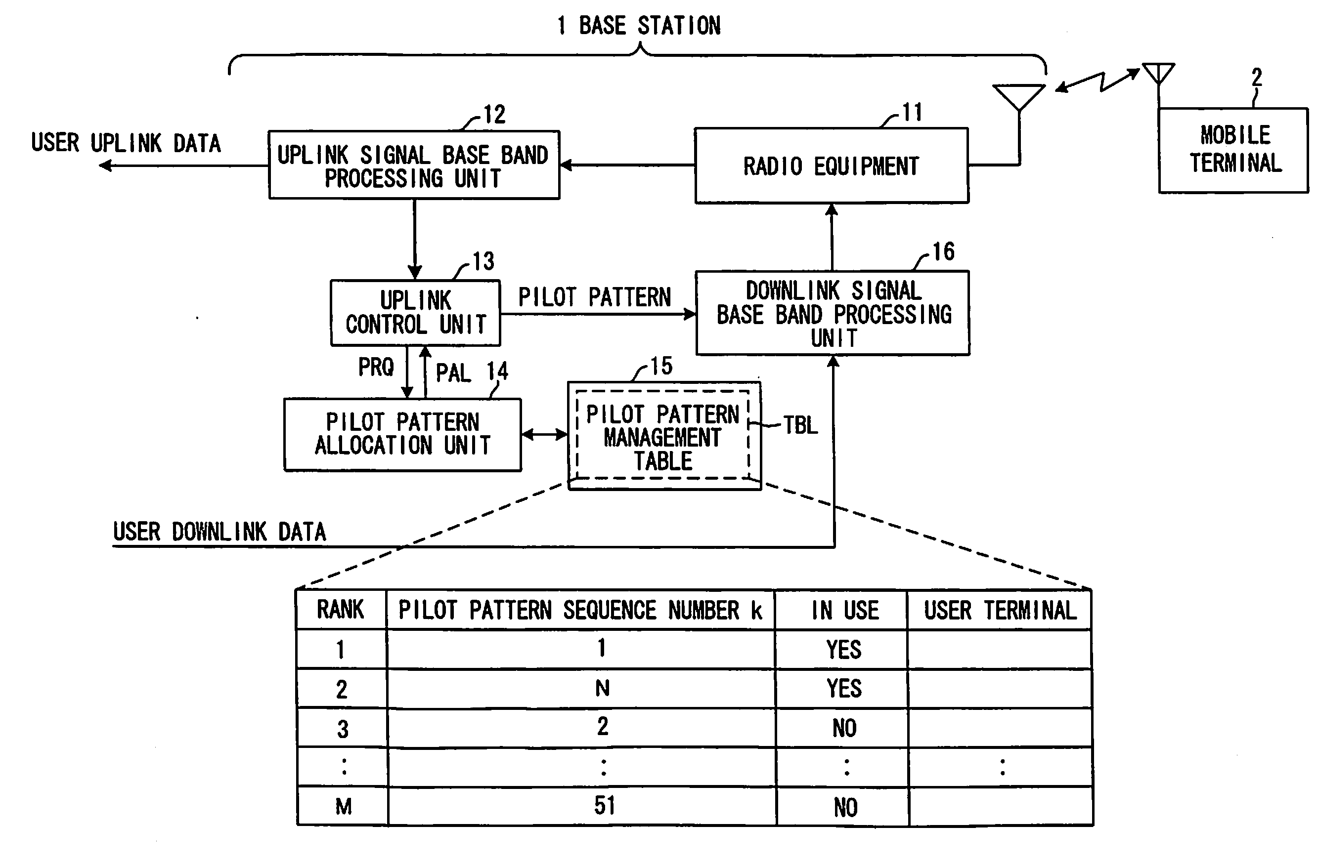
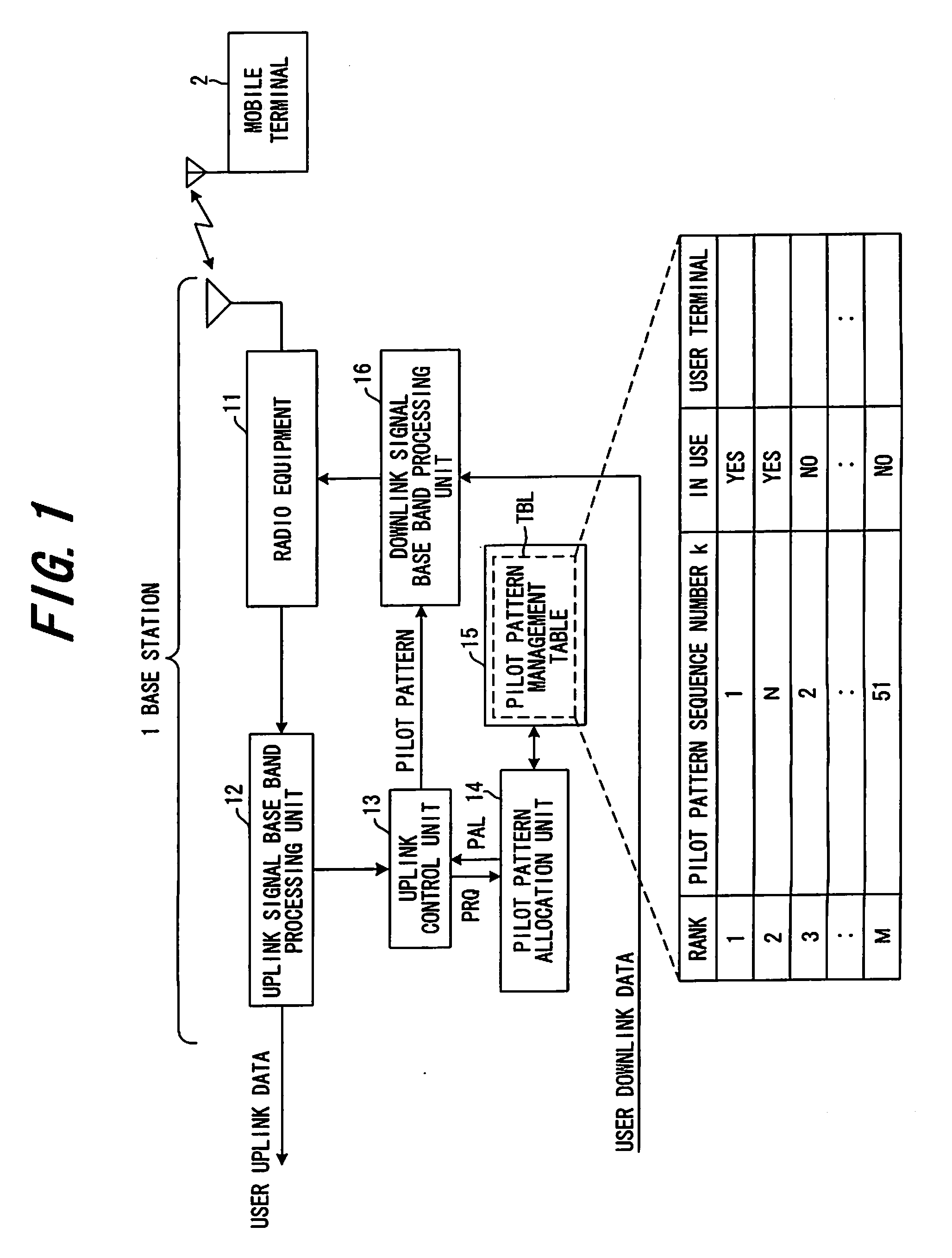
[0063]FIG. 1 is a block diagram of a base station according to a first embodiment, where a base station 1 stores a rank table on a peak to average power ratio of each pilot pattern, and allocates a pilot in order of goodness of peak to average power ratio to a user terminal 2 when a connection is established with the user terminal 2.

[0064]A radio equipment 11 has a transmitter and a receiver, and the receiver converts the frequency of a receive signal from a radio frequency into a base bandfrequency, and inputs the base band signal to an uplink signal base band processing unit 12. The base band processing unit 12 performs demultiplexing and demodulating of user data and control data from the input signal, and inputs the control data to an uplink control unit 13. The uplink control unit 13 requests a pilot pattern allocation unit 14 to allocate a pilot pattern using a signal PRQ when a connection is set.

[0065]When each pilot pattern of a CAZAC sequence is ranked b...

second embodiment

(B) Second Embodiment

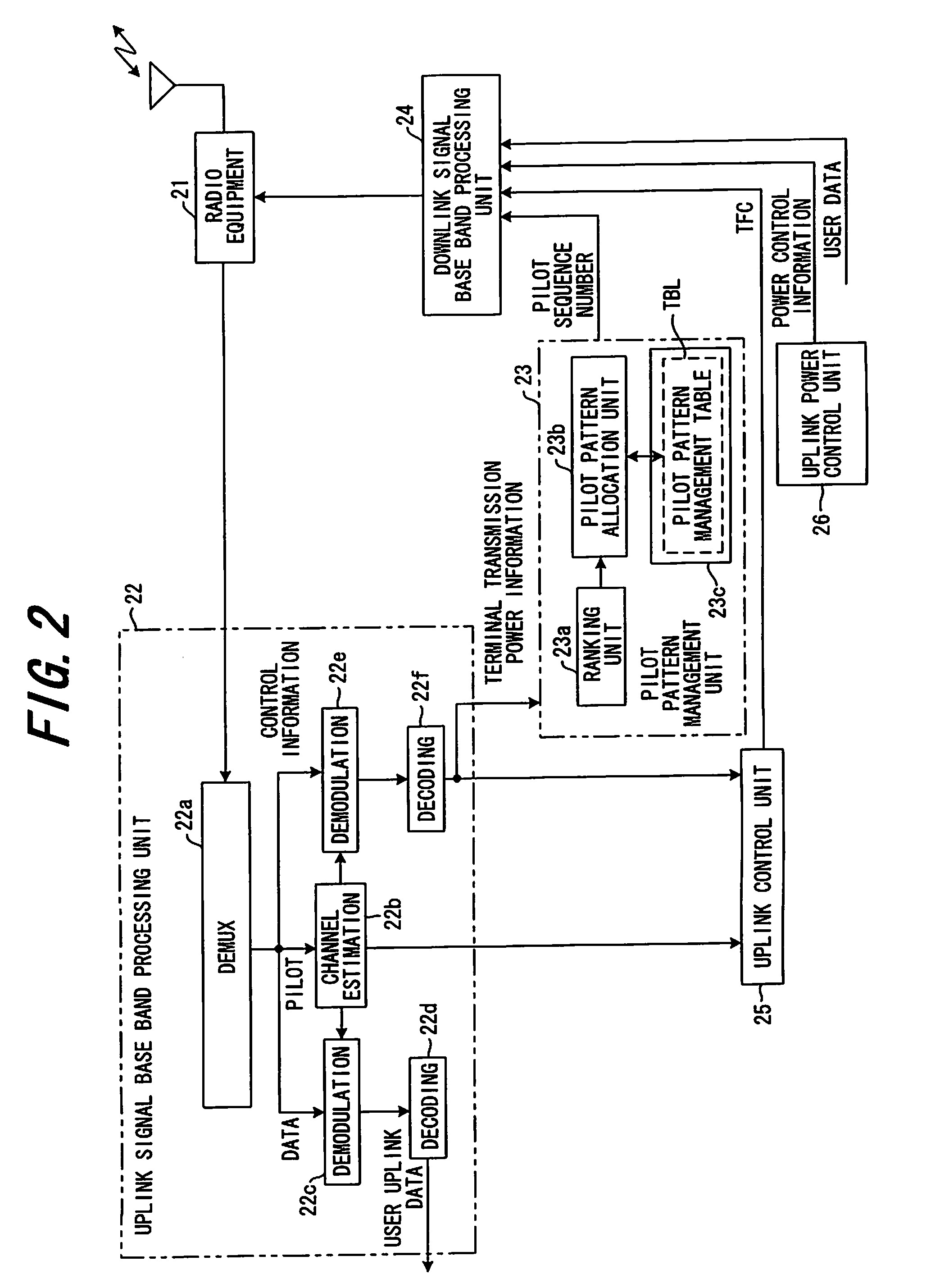
[0069]FIG. 2 is a block diagram of a base station according to the second embodiment. In the second embodiment, a pilot pattern is decided based on the transmission power of the user terminal.

[0070]A radio equipment 21 includes a transmitter and a receiver, which are not illustrated, and the receiver converts a frequency of a receive signal from a radio frequency into a base band frequency, and inputs the base band signal to an uplink signal base band processing unit 22. The signal format consists of a pilot PL, control information CNT, user data DT, and CRC for error detection, for example, as shown in FIG. 3.

[0071]A demultiplexing unit 22a of the base band processing unit 22 demultiplexes a pilot, user data and control data from the input signal, a channel estimation unit 22b estimates a channel (transmission path characteristic) using the pilot signal and outputs a channel estimation value, a demodulation unit 22c performs channel compensation based on the ch...

third embodiment

(C) Third Embodiment

[0085]FIG. 6 is a block diagram of a base station according to a third embodiment, where the same components as those in the second embodiment in FIG. 2 are denoted with the same reference symbols.

[0086]Since the transmission power of a user terminal increases as the user terminal becomes more distant from the base station, a pilot pattern is decided based on the position information (distance from the base station) of the user terminal in the third embodiment.

[0087]A receiver of a radio equipment 21 converts a frequency of a receive signal from a radio frequency into a base band frequency, and inputs the base band signal to an uplink signal base band processing unit 22. The base band processing unit 22 demultiplexes a pilot, user data and control data from the input signal, and inputs control information to a terminal information processing unit 27. The terminal information processing unit 27 extracts position information of a user terminal from the control info...


PUM


Abstract

In a radio communication system which uses pilot signals during transmission from a user terminal to a base station, the base station creates and stores a rank table on a peak to average power ratio of each pilot pattern, extracts a transmission power of the user terminal or a power difference between a maximum transmission power and the transmission power of the user terminal on the basis of a receive signal from the user terminal, and allocates a pilot pattern of which peak to average power ratio is good to a user terminal of which transmission power is great, or the power difference is small, with reference to the rank table.
Or a pilot pattern in a rank according to the transmission status (e.g. transmission power, distance from the base station) of the user terminal is adaptively allocated to the user terminal.

Description

BACKGROUND OF THE INVENTION[0001]The present invention relates to a base station, a radio communication system and a pilot pattern decision method, and more particularly to a base station in a radio communication system which uses pilot signals having a predetermined pilot pattern during transmission from a user terminal to the base station, and a pilot pattern decision method of the base station.[0002]In a radio communication system, such as a cellular system, data is demodulated by synchronization and channel estimation using a known pilot signal. In the case where adaptive modulation is used, a pilot signal is also used for estimating a signal to interference power ratio (SIR) to decide an optimum modulation system.[0003]In the case of an uplink from a user terminal to a base station, a pilot pattern which has a good correlation characteristic is used as a pilot signal, so as to minimize interference from another user and multi-path interference.[0004]FIG. 27 is a diagram depicti...

Claims


Application Information

Patent Timeline
IPC IPC(8): H04Q7/20H04M1/00H04W52/32
CPCH04W52/325H04L5/0048H04L5/0091H04B17/382H04L5/0073H04B17/309H04L27/262
Inventor SHIMOMURA, TSUYOSHIKIMURA, DAI
Owner FUJITSU LTD
Why Eureka
Try Eureka