3D MIMI transmission method and device
A reference resource and signaling technology, applied in the field of channel state measurement and feedback, downlink channel state measurement and feedback solutions, can solve the problems of large number of physical antennas, unacceptable air interface overhead, and time-frequency resource occupation
- Summary
- Abstract
- Description
- Claims
- Application Information
AI Technical Summary
Problems solved by technology
Method used
Image
Examples
Embodiment 1
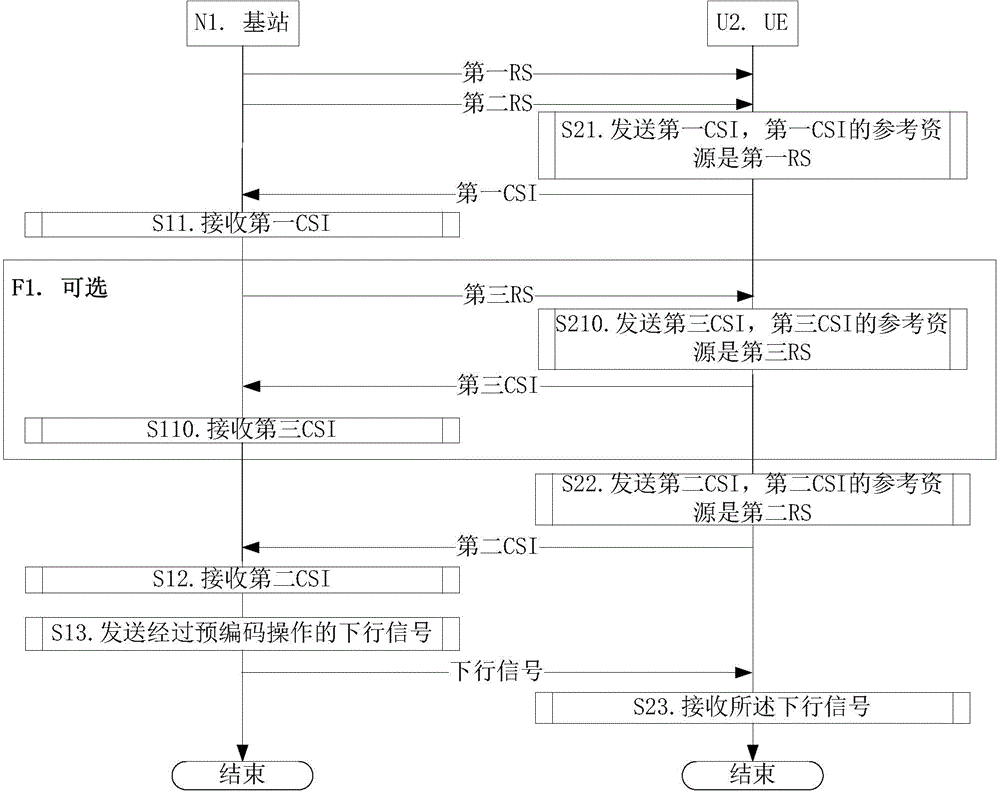
[0101] Embodiment 1 is a CSI feedback flow chart, as attached figure 2 shown. attached figure 2 In , base station N1 is the serving base station of UEU2. The steps identified in box F1 are optional steps.
[0102] For UEU2, in step S21, the first CSI is sent; in step S21, the second CSI is sent; in step S23, the downlink signal after the precoding operation is received.
[0103] For the base station N1, in step S11, the first CSI is received; in step S12, the second CSI is received; in step S13, the precoded downlink signal is sent.
[0104] In Embodiment 1, the reference resource of the first CSI is the first RS, the first CSI includes the first PMI, and the first RS is broadband; the reference resource of the second CSI is the second RS, and the second CSI includes the second PMI and At least one of the second CQI, the second RS is narrowband. The first RS and the second RS are sent by the same cell, and the cell is maintained by the base station N1. The precoding ma...
Embodiment 2
[0109] Embodiment 2 is a schematic diagram of the time domain positions of the first RS and the second RS, as shown in the attached image 3 shown. attached image 3 In , the squares marked with oblique lines are the subframes in the CSI subframe set to which the first RS belongs, and the squares marked with bold lines are the subframes in the CSI subframe set to which the second RS belongs.
[0110] The CSI subframe set to which the first RS belongs is the first CSI subframe set (composed of squares marked with slashes), and the CSI subframe set to which the second RS belongs is the second CSI subframe set (squares marked with thick lines). composition). The first CSI subframe set and the second CSI subframe set are configured by high layer signaling.
[0111] As a sub-embodiment of Embodiment 2, the first RS is sent on all subframes in the first CSI subframe set, and the second RS is sent on only one subframe in the second CSI subframe set.
[0112] The essence of the ab...
Embodiment 3
[0114] Embodiment 3 is a schematic diagram of the time-frequency position of the second RS, as shown in the attached Figure 4 shown. attached Figure 4 , the squares marked with slashes are PRBP groups, and the squares marked with bold lines are PRBP groups occupied by the second RS.
[0115] The base station first sends the first signaling to indicate L PRBP groups; then, according to the time domain position of the second RS, it is determined that one target PRBP group in the L PRBP groups is the PRBP occupied by the second RS.
[0116] The UE first receives the first signaling to determine L PRBP groups; then determines that one target PRBP group in the L PRBP groups is the PRBP occupied by the second RS according to the time domain position of the second RS.
[0117] In Embodiment 3, the first signaling is high-level signaling, and the L is a positive integer greater than 1. The PRBP group includes a positive integer number of continuous PRBPs in the frequency domain. ...
PUM
 Abstract
Description
Claims
Application Information
 - R&D
- Intellectual Property
- Life Sciences
- Materials
- Tech Scout
- Unparalleled Data Quality
- Higher Quality Content
- 60% Fewer Hallucinations
Browse by: Latest US Patents, China's latest patents, Technical Efficacy Thesaurus, Application Domain, Technology Topic, Popular Technical Reports.
© 2025 PatSnap. All rights reserved.Legal|Privacy policy|Modern Slavery Act Transparency Statement|Sitemap|About US| Contact US: help@patsnap.com


