DTV transmitting system and method of processing broadcast data

a technology of broadcast data and transmitting system, which is applied in the field of broadcast data processing in television systems and methods, can solve the problems of data that is to be transmitted should have a low error ratio, the quality of the received digital signals may be deteriorated, and the signal intensity may decrease, so as to improve the quality of the receiving system and enhance the transmission quality

Inactive Publication Date: 2010-06-15
LG ELECTRONICS INC
View PDF242 Cites 48 Cited by
  • Summary
  • Abstract
  • Description
  • Claims
  • Application Information

AI Technical Summary

Benefits of technology

[0010]The present invention is to provide a DTV transmitting system and a method of processing broadcast that can perform additional encoding on enhanced data and transmit the additionally encoded enhanced data, thereby enhancing the receiving quality of the receiving system.
[0011]The present invention is to provide a DTV transmitting system and a method of processing broadcast that can multiplex the known data and enhanced data, thereby enhancing the receiving quality of the receiving system.

Problems solved by technology

However, when used indoors, the intensity of the signals may decrease due to a blockage caused by the walls or disturbance caused by approaching or proximate mobile objects.
Accordingly, the quality of the received digital signals may be deteriorated due to a ghost effect and noise caused by reflected waves.
However, unlike the general video / audio data, when transmitting the supplemental data, the data that is to be transmitted should have a low error ratio.
Conversely, in case of the supplemental data (e.g., program execution file, stock information, etc.), an error even in a single bit may cause a serious problem.
Furthermore, in a poor channel environment, the receiving performance of the conventional receiving system may be deteriorated.

Method used


Image

  • DTV transmitting system and method of processing broadcast data
  • DTV transmitting system and method of processing broadcast data
  • DTV transmitting system and method of processing broadcast data

Examples


first embodiment

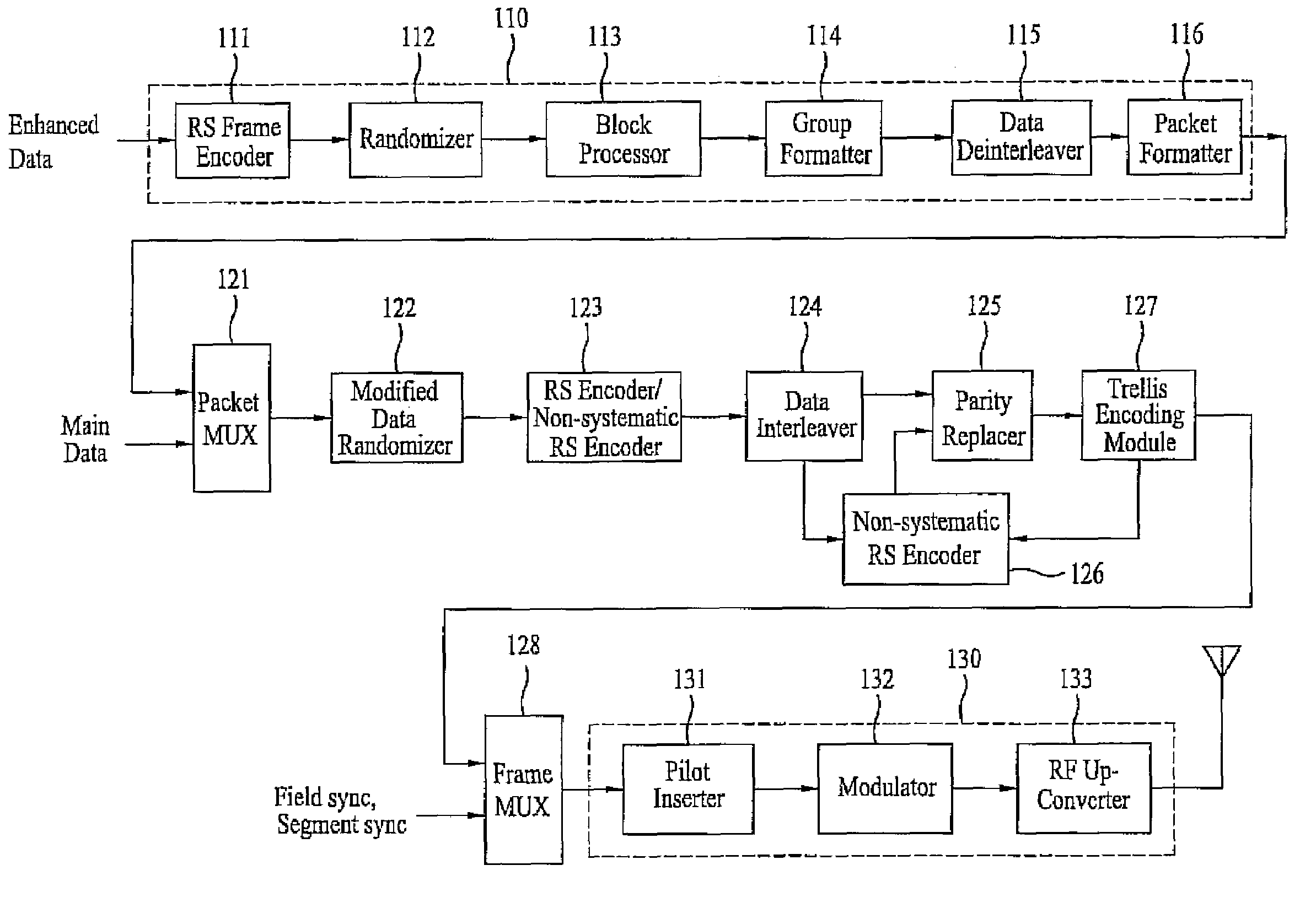
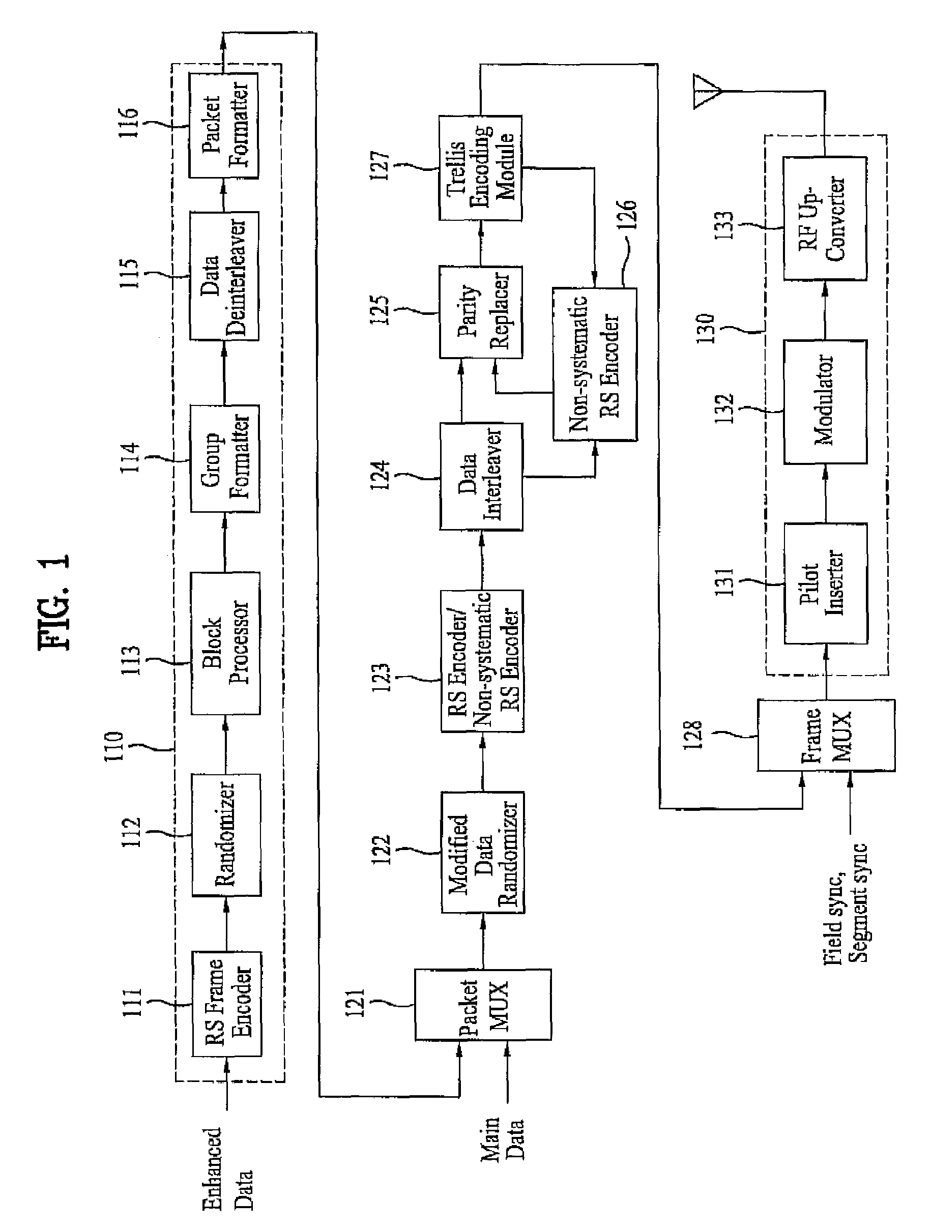
[0031]FIG. 1 illustrates a block diagram showing a structure of a digital television transmitting system according to a first embodiment of the present invention. Referring to FIG. 1, the digital television transmitting system includes a pre-processor 110, a packet multiplexer 121, a data randomizer 122, a Reed-Solomon (RS) encoder / non-systematic RS encoder 123, a data interleaver 124, a parity replacer 125, a non-systematic RS encoder 126, a trellis encoding module 127, a frame multiplexer 128, and a transmitting unit 130. The pre-processor 110 includes a RS frame encoder 111, an enhanced data randomizer 112, a block processor 113, a group formatter 114, a data deinterleaver 115, and a packet formatter 116.

[0032]In the present invention having the above-described structure, the main data is inputted to the packet multiplexer 121, and the enhanced data is putted to the pre-processor 110 which performs additional encoding, so that the enhanced data can take strong countermeasures aga...

second embodiment

[0064]FIG. 8 illustrates a block diagram showing a structure of a digital television transmitting system according to a second embodiment of the present invention. Referring to FIG. 5, the digital television transmitting system includes a pre-processor 510, a packet multiplexer 121, a data randomizer 122, a Reed-Solomon (RS) encoder / non-systematic RS encoder 123, a data interleaver 124, a parity replacer 125, a non-systematic RS encoder 126, a trellis encoding module 127, a frame multiplexer 128, and a transmitting unit 130. The pre-processor 510 includes a RS frame encoder 511, a randomizer / byte expander 512, a group formatter 513, a block processor 514, a data deinterleaver 515, and a packet formatter 516.

[0065]The difference between the digital television transmitting system shown in FIG. 1 and the digital television transmitting system shown in FIG. 8 is the arrangement order of the group formatter and the block processor. In FIG. 1, the group formatter 114 is placed after the b...


PUM


Abstract

A DTV transmitting system includes an encoder, a randomizer, a block processor, a group formatter, a deinterleaver, and a packet formatter. The encoder codes enhanced data for error correction, permutes the coded data, and further codes the permuted data for error detection. The randomizer randomizes the coded enhanced data, and the block processor codes the randomized data at an effective coding rate of 1 / H. The group formatter forms a group of enhanced data having data regions, and inserts the coded enhanced data into at least one of the data regions. The deinterleaver deinterleaves the group of enhanced data, and the packet formatter formats the deinterleaved data into corresponding data bytes.

Description

[0001]This application claims the benefit of the Korean Patent Application No. 10-2006-0039118, filed on Apr. 29, 2006, which is hereby incorporated by reference as if fully set forth herein. Also, this application claims the benefit of the Korean Patent Application No. 10-2006-0089736, filed on Sep. 15, 2006, which is hereby incorporated by reference as if fully set forth herein. This application also claims the benefit of U.S. Provisional Application No. 60 / 821,251, filed on Aug. 2, 2006, which is hereby incorporated by reference.BACKGROUND OF THE INVENTION[0002]1. Field of the Invention[0003]The present invention relates to television systems and methods of processing broadcast data.[0004]2. Discussion of the Related Art[0005]Presently, the technology for processing digital signals is being developed at a vast rate, and, as a larger number of the population uses the Internet, digital electric appliances, computers, and the Internet are being integrated. Therefore, in order to mee...

Claims


Application Information

Patent Timeline
Patent Type & Authority Patents(United States)
IPC IPC(8): H03M13/00
CPCH04L1/0041H04L1/0047H04L1/0054H04L1/0065H04L1/007H04L1/0071H04L1/0061H04N21/23614H04N21/2383H04N21/4348H04N21/435H04N21/4382H03M13/1515H04N21/235H03M13/2703H03M13/6522H03M13/2792H04L1/0058
Inventor LEE, HYOUNG GONCHOI, IN HWANKWAK, KOOK YEONKIM, JONG MOONSONG, WON GYUKIM, BYOUNG GILLKIM, JIN WOO
Owner LG ELECTRONICS INC
Why Eureka
Try Eureka