Sewing machine

a sewing machine and needle technology, applied in the field of sewing machines, can solve the problems of troublesome needle replacement and inability to reliably form cuts in workpiece cloths

Active Publication Date: 2015-09-10
BROTHER KOGYO KK
View PDF6 Cites 1 Cited by
  • Summary
  • Abstract
  • Description
  • Claims
  • Application Information

AI Technical Summary

Benefits of technology

[0007]Therefore, an object of the disclosure is to provide a sewing machine which can desirably cut the workpiece cloth with the floating of the workpiece cloth being suppressed when the workpiece cloth is cut by the cutwork device provided on the sewing machine bed.
[0008]The disclosure provides a sewing machine including a sewing machine head including a needle bar to which a sewing needle is attachable, a sewing machine bed having an upper surface on which a workpiece cloth is placed so that sewing may be performed on the workpiece cloth, a cutwork device provided on the sewing machine bed and including a cutting needle with a distal end having a blade and a cutting needle up-down movement mechanism moving the cutting needle up and down, the cutwork device being configured to form a cut in the workpiece cloth by the cutting needle at a cutting position from below the workpiece cloth, the cutting position being spaced a predetermined distance rearward from a needle location of the sewing needle on the sewing machine bed, and a catching member configured to suppress upward floating of the workpiece cloth caused by the cutting needle during operation of the cutwork device.

Problems solved by technology

The replacement of the needles is troublesome.
More specifically, when the workpiece cloth floats, it is expected that cuts cannot reliably be formed in the workpiece cloth.

Method used


Image

  • Sewing machine
  • Sewing machine
  • Sewing machine

Examples


Embodiment Construction

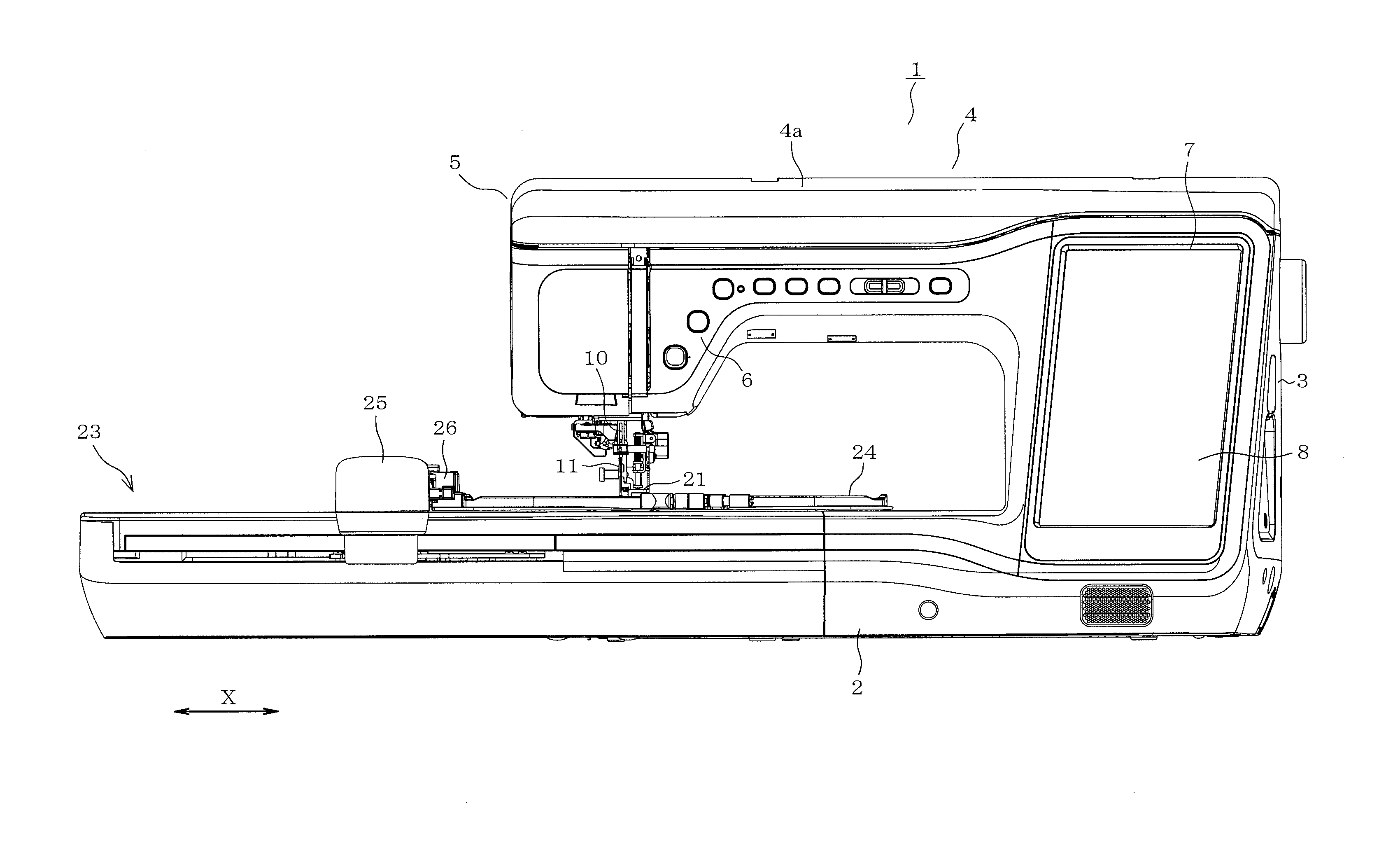
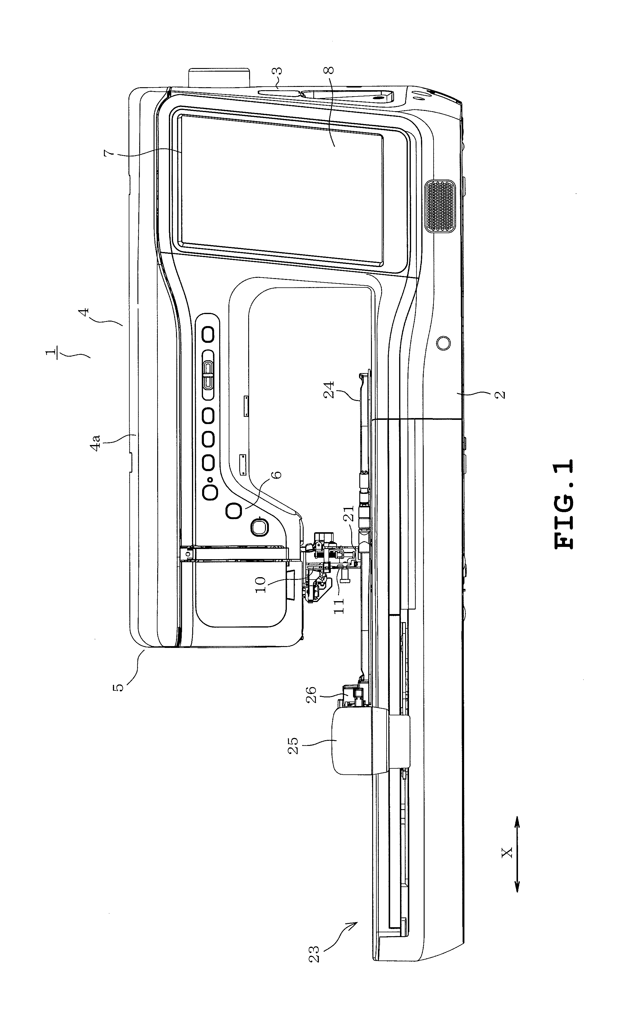
[0026]An embodiment will be described with reference to the drawings. The embodiment is applied to a household sewing machine which is capable of sewing an embroidery pattern. Referring to FIG. 1, an overall sewing machine 1 is shown to which an embroidering machine 23 which will be described later is attached. The sewing machine 1 includes a sewing machine bed 2 extending in a right-left direction (X direction). A pillar 3 extends upward from a right end of the sewing machine bed 2. An arm 4 extends leftward from an upper end of the pillar 3 as viewed in FIG. 1. The arm 4 has a distal end serving as a sewing machine head 5. The sewing machine bed 2 and the sewing machine head 5 will be abbreviated as “bed” and “head” in the following description respectively. In the following description, the side where a user is located relative to the sewing machine 1 will be referred to as “front” of the sewing machine. The side located opposite the front will be referred to as “rear.” The side ...


PUM


Abstract

A sewing machine includes a sewing machine head including a needle bar to which a sewing needle is attachable, a sewing machine bed having an upper surface on which a workpiece cloth is disposed in order that sewing may be performed for the workpiece cloth, a cutwork device located on the sewing machine bed and including a cutting needle with a distal end having a blade and a cutting needle up-down movement mechanism moving the cutting needle up and down, and a catching member suppressing upward floating of the workpiece cloth caused by the cutting needle during operation of the cutwork device. The cutwork device forms a cut in the workpiece cloth by the cutting needle at a cutting position from below the workpiece cloth. The cutting position is spaced a predetermined distance rearward from a needle location of the sewing needle on the sewing machine bed.

Description

CROSS-REFERENCE TO RELATED APPLICATIONS[0001]This application is based upon and claims the benefit of priority from the prior Japanese Patent Application No. 2014-043871 filed on Mar. 6, 2014, the entire contents of which are incorporated herein by reference.BACKGROUND[0002]1. Technical Field[0003]The present disclosure relates to a sewing machine in which a needle bar to which a sewing needle is attached is mounted on a sewing machine head, the sewing machine performing sewing on a workpiece cloth placed on a sewing machine bed.[0004]2. Related Art[0005]Sewing machines have conventionally been provided which can cut a workpiece cloth. In these sewing machines, a sewing needle attached to a needle bar is detached and a cutting needle and a cloth-pressing spring are attached to the needle bar. This allows the needle bar to be moved up and down so that the cutting needle forms cuts in the workpiece cloth, with the result that the workpiece cloth can be cut.SUMMARY[0006]The user needs ...

Claims


Application Information

Patent Timeline
Patent Type & Authority Applications(United States)
IPC IPC(8): D05B37/04D05C13/00D05C3/02
CPCD05B37/04D05D2305/08D05C13/00D05C3/02B26F1/02D05B37/063D05B37/066D05C7/04D06H7/00
Inventor UEDA, DAISUKEOSAMURA, TAKAHIRA
Owner BROTHER KOGYO KK
Why Eureka
Try Eureka