Stackable wire-dispensing container

a container and wire technology, applied in the field of electrical wire and cables, can solve the problems of compromising the stability of the coil, and achieve the effects of reducing the pulling force needed to disperse the wire, high total footage capacity, and convenient transportation or carrying

Active Publication Date: 2018-11-20
ENCORE WIRE CORP
View PDF54 Cites 1 Cited by
  • Summary
  • Abstract
  • Description
  • Claims
  • Application Information

AI Technical Summary

Benefits of technology

[0009]The present invention provides for a stackable wire dispensing container. The stackable wire dispensing container contains a coil of wire and allows the wire to be dispensed without requiring the rotation of the entire coil and package. The removal of the need to rotate the entire reel or spool significantly reduces the pulling force needed to dispense the wire. The stackable wire dispensing container includes a handle or handles to provide ease in transporting or carrying the stackable wire dispensing container containing the wire. Finally, the stackable wire dispensing container may be conveniently stacked in any number for convenient payoff of several wires or wire types or sizes simultaneously or during the same wire pull by the user. The stackable wire dispensing container is advantageous over prior art containers due to the containers' high total footage capacity and typically lower cost as a wide variety of materials may be used in the manufacture of the stackable wire dispensing container without detracting from the spirit of the invention, including less expensive materials. Further, the stackable wire dispensing container uses a standard coiling machine and does not require a FIG. 8 pattern of coiling of wire. Additionally, the stackable wire dispensing container removes the need to unwrap or cut the shrink-wrap to dispense the wire. When cutting a shrink-wrapped coil, it is easy to make a hole that is too large and will compromise the stability of the coil. The precut payoff holes of the stackable wire dispensing container provide more stability and convenience.

Problems solved by technology

When cutting a shrink-wrapped coil, it is easy to make a hole that is too large and will compromise the stability of the coil.

Method used


Image

  • Stackable wire-dispensing container
  • Stackable wire-dispensing container
  • Stackable wire-dispensing container

Examples


Embodiment Construction

[0025]The following discussion is presented to enable a person skilled in the art to make and use the present invention. The general principles described herein may be applied to embodiments and applications other than those specifically detailed below without departing from the spirit and scope of the present invention. Therefore, the present invention is not intended to be limited to the embodiments expressly shown, but is to be accorded the widest possible scope of invention consistent with the principles and features disclosed herein.

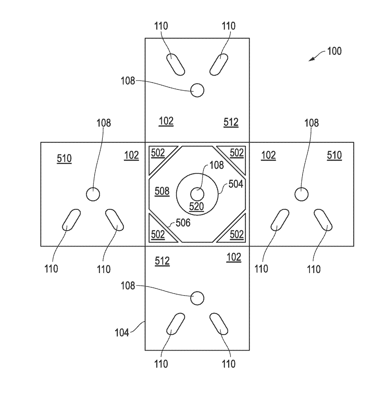
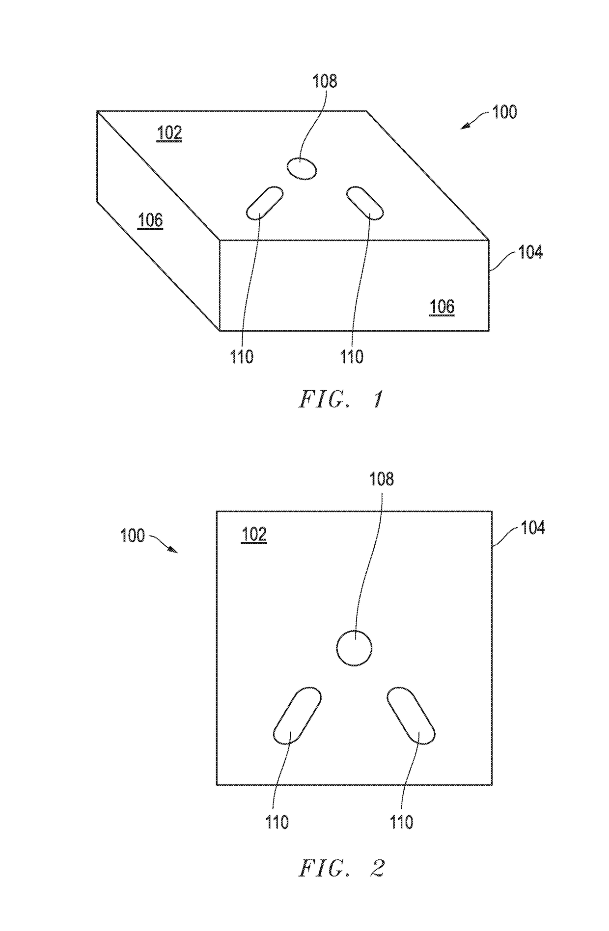
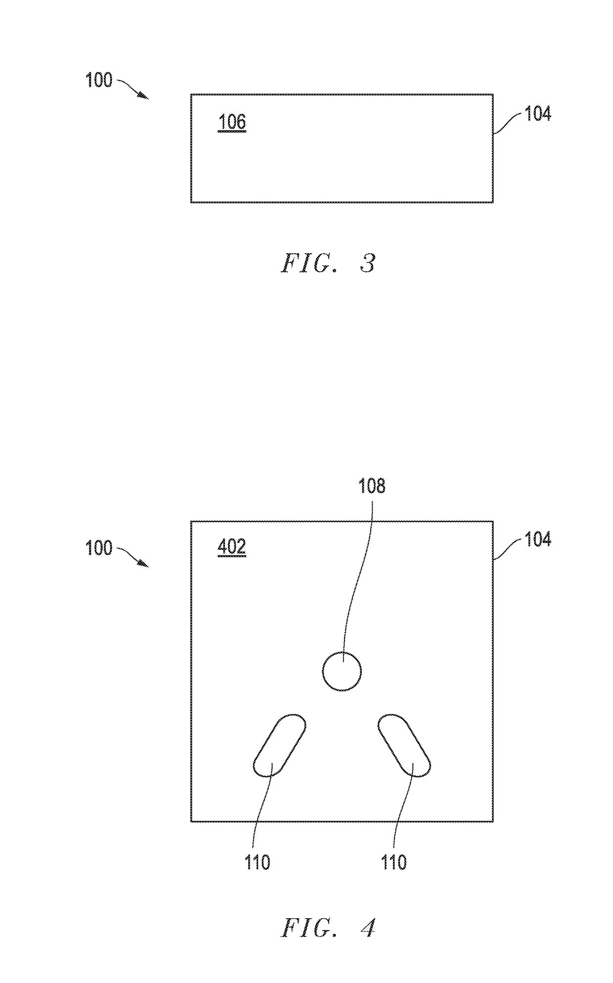
[0026]Referring to FIGS. 1-7 by way of non-limiting example, and consistent with embodiments of the invention, a stackable wire dispensing container 100 is shown. According to one embodiment of the invention, a stackable wire dispensing container 100 includes three components—a box enclosure 104, a core 504, and support elements 502. In one embodiment, the box enclosure 104 is formed by a single sheet of corrugated cardboard, which is appropriately ...


PUM


Abstract

An apparatus for dispensing wire or cable, the apparatus including an enclosure with a top and a bottom portion and at least three side portions of a first height, a plurality of holes located in both the top and bottom portions of the enclosure, and a core of a second height located within the enclosure, wherein the core forms an area, wherein at least one of the plurality of holes has a first hole diameter and is located in the top and bottom of the enclosure and is located within the area formed by the core, and wherein the wire or cable is placed around the core.

Description

CROSS-REFERENCE TO RELATED APPLICATIONS[0001]This application claims priority benefit to U.S. Provisional Patent Application No. 62 / 273,926, filed Dec. 31, 2015, which is hereby incorporated by reference herein.STATEMENT REGARDING FEDERALLY SPONSORED RESEARCH OR DEVELOPMENT[0002]Not applicable.REFERENCE TO A COMPACT DISK APPENDIX[0003]Not applicable.BACKGROUND OF THE INVENTION1. Field of the Invention[0004]The present invention relates in general to electrical wire and cable, and more particularly, to the stackable wire dispensing containers.2. Description of Related Art[0005]Wooden reels or plastic and metal spools are common in the wire and cable industry for winding circuit-size wire. Once wound, the reels and spools are distributed to customers for use at jobsites. Wound reels and spool are often heavy, cumbersome and difficult to carry while on the jobsite due to a lack of a handle. External conditions may also impact the reliability of the reel or spool. For example, in wet co...

Claims


Application Information

Patent Timeline
Patent Type & Authority Patents(United States)
IPC IPC(8): B65H49/16B65D85/04B65H75/12B65D21/02B65H49/08
CPCB65D21/0209B65D85/04B65H75/12B65H49/16B65H49/08B65H2701/34B65H2701/534
Inventor WEATHERFORD, BENJAMIN L.BIGBEE, JR., WILLIAM T.THOMPSON, CLIFTON S.
Owner ENCORE WIRE CORP
Why Eureka
Try Eureka