Fluid power distribution and control system

a technology of power distribution and control system, applied in the direction of fluid clutch, fluid-pressure actuator, fluid coupling, etc., can solve the problems of energy loss, unsatisfactory compromise, and the overall efficiency of such a system to reduce to 30%

Active Publication Date: 2018-12-25
DANFOSS PAUER SOLYUSHENS APS
View PDF21 Cites 67 Cited by
  • Summary
  • Abstract
  • Description
  • Claims
  • Application Information

AI Technical Summary

Benefits of technology

[0008]The system uses the ability of pumps according to EP 0361 927 B1 or pump / motors according to EP 0494236 B1 to provide a number of independent and fully controllable fluid supplies from one compact package with a single input shaft. By coupling combinations of these supplies to the loads, the control of multiple independent loads can be achieved at higher energy efficiency.
[0015]Individual fluid supplies from a Digital Displacement pump can be switched quickly from being controlled by a flow demand to being controlled by a pressure demand, the latter being achieved using a control loop with feedback from a pressure transducer.

Problems solved by technology

In systems with a single pump and multiple actuators there is always undesirable compromise given the practical impossibility of matching the instantaneous pressure requirements of all of the active actuators to the single pressure supply.
The difference between this pressure and the actual pressure required of any one of the loads is throttled in a proportional valve, creating energy losses.
However when multiple actuators must be moved simultaneously at different pressures then the efficiency becomes poor—depending on the duty cycle, these losses can cause the overall efficiency of such a system to reduce to 30%.

Method used


Image

  • Fluid power distribution and control system
  • Fluid power distribution and control system
  • Fluid power distribution and control system

Examples


Embodiment Construction

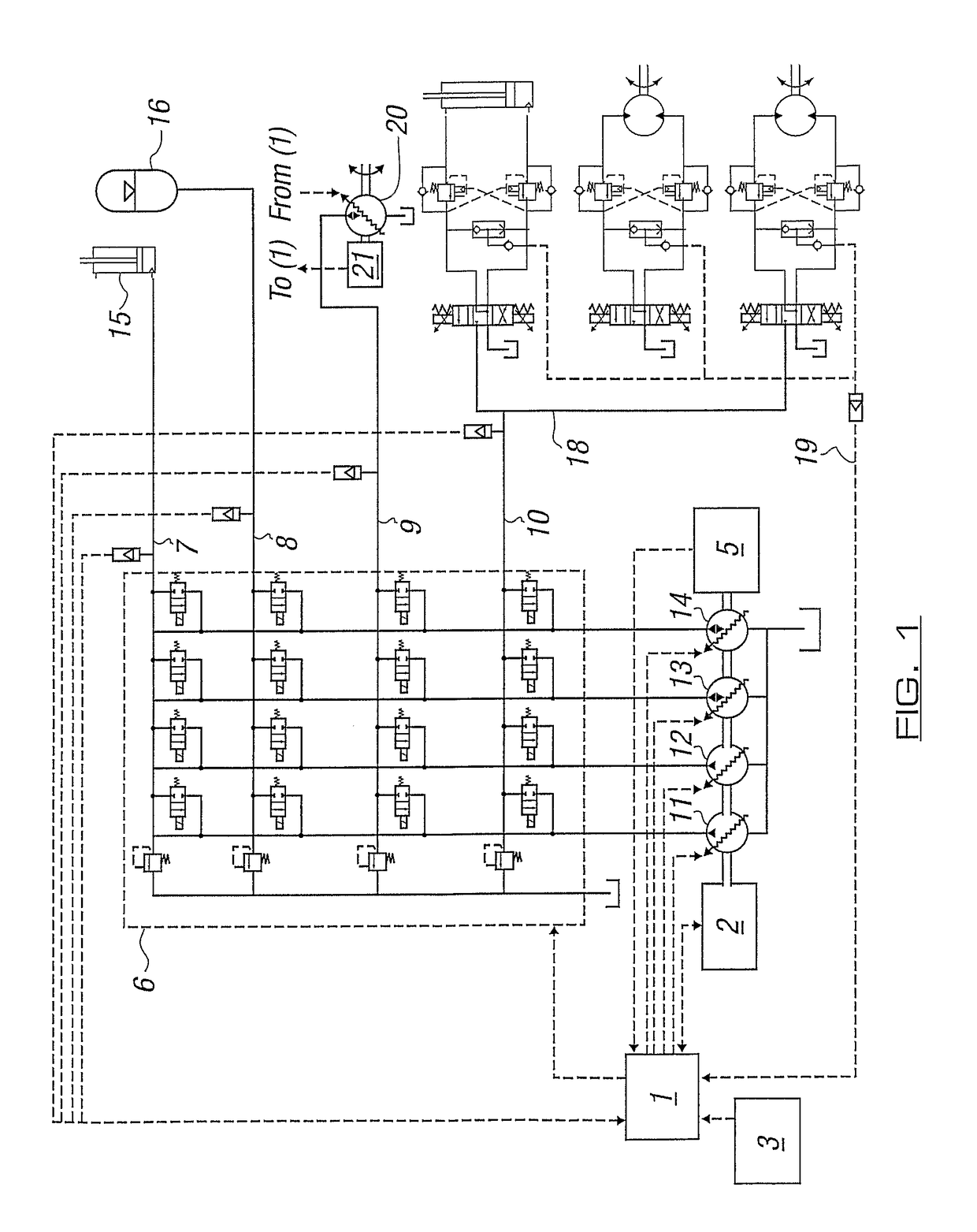
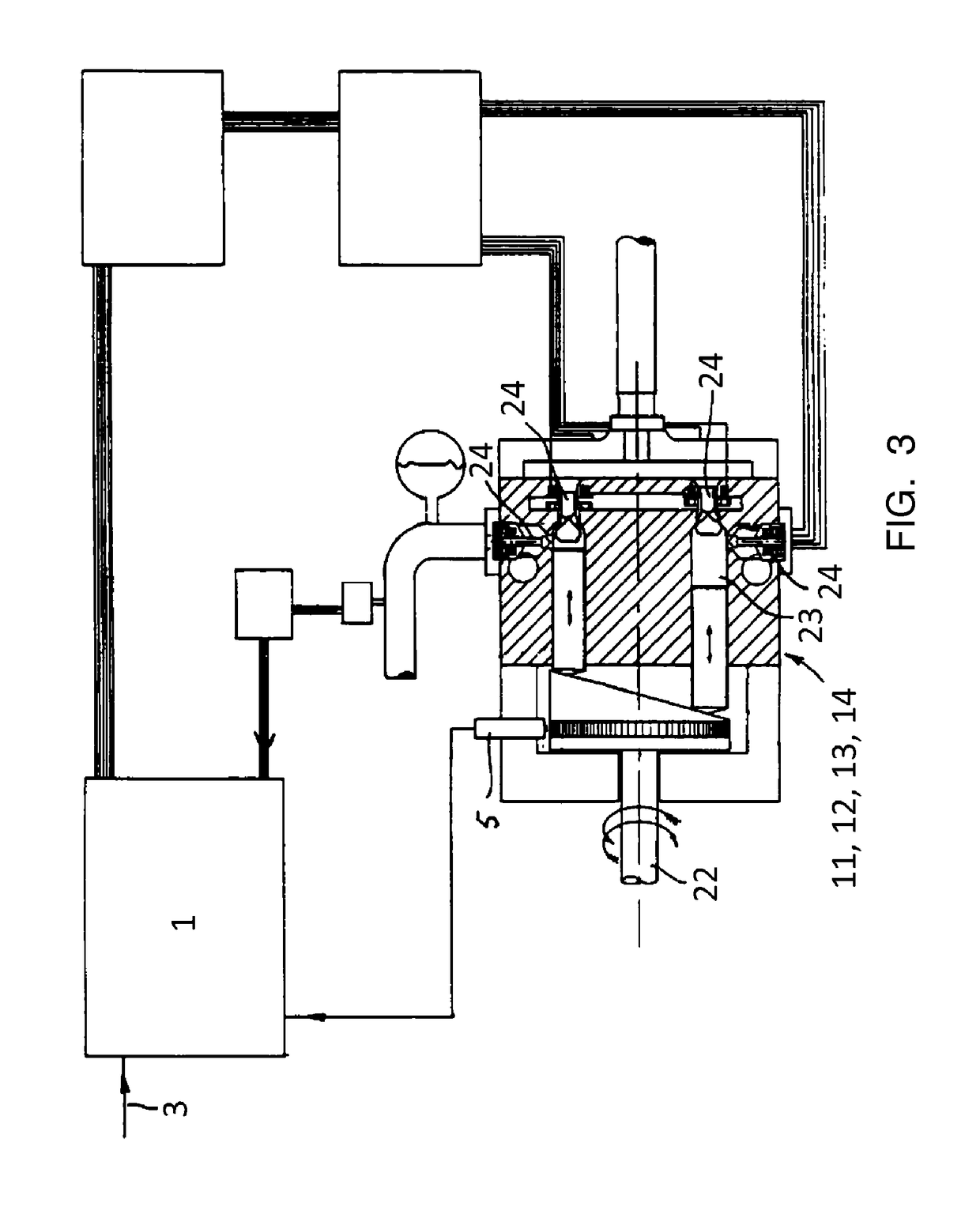
[0022]The drawing shows a pump / motor with four independent fluid supplies, two of which 11, 12 are pump outlets, two of which 13, 14 are pump / motor outlets, and each of which is controlled by a controller 1. Mechanical power comes into the pump / motor unit via its shaft 22 from a prime mover 2, which may take a speed demand signal from the controller 1. The fluid working machines 11, 12, 13, 14 may be configured as pumps according to EP 0361 927 B1 or pump / motors according to EP 0494236 B1. Each fluid working machine 11, 12, 13, 14 comprises one or more working chambers 23 and one or more commutating valves 24. A control system 1 is provided to supply pulses to the commutating valves 24 of the fluid working machines 11, 12, 13, 14. The pump / motor unit uses the ability of pumps according to EP 0361 927 B1 or pump / motors according to EP 0494236 B1 to provide a number of independent and fully controllable fluid supplies from one compact package with a single input shaft 22.

[0023]The swi...


PUM


Abstract

A fluid power system comprises a pump with multiple independently variable outlets (11, 12, 13, 14), each of which is capable of delivering fluid in individually controllable volume units and a plurality of hydraulic loads (15, 16, 18, 20). A system of switching valves is configured to create fluid connections between the pump outlets and the loads. A control system commands both the pump and the switching valves, so as to create valve state combinations to satisfy load conditions as demanded by an operator. The number of pump outlets (11, 12, 13, 14) connected to one or more of the loads (15, 16, 18, 20) is changeable to satisfy the flow required of the load due to the operator demand, each pump outlet being commanded to produce a flow depending on the status of other outlets connected a load to which the outlet is connected and the operator demand for that load.

Description

PRIORITY APPLICATIONS[0001]This application is a 371 application of International Application No. PCT / GB2007 / 002747 filed Jul. 19, 2007, which claims priority to United Kingdom Patent Application No. 0614534.6 filed Jul. 21, 2006. The entire disclosure of each of the foregoing applications is hereby incorporated herein by reference.BACKGROUND TO THE INVENTION[0002]This invention relates to a fluid power system.[0003]In their most basic form, fluid power systems generally consist of a pressurised fluid source, a motion control valve and an actuator such as a ram or a motor. Systems are typically generalised by attaching further motion control valves in parallel to the first so that additional actuators can be moved with the power supplied by the fluid source. Because most actuators have a fixed linear or rotary movement per unit of fluid displacement, the force they exert is directly proportional to the pressure supplied. In systems with a single pump and multiple actuators there is ...

Claims


Application Information

Patent Timeline
Patent Type & Authority Patents(United States)
IPC IPC(8): F15B11/17F15B11/044F15B11/16
CPCF15B11/17F15B11/162F15B11/0445F15B2211/7058F15B2211/20546F15B2211/20569F15B2211/20576F15B2211/265F15B2211/2656F15B2211/3127F15B2211/327F15B2211/5059F15B2211/6052F15B2211/6054F15B2211/633F15B2211/6313F15B2211/6346F15B2211/7052F15B2211/7053
Inventor RAMPEN, WILLIAM HUGH SALVINCALDWELL, NIALL JAMESSTEIN, UWE BERNHARD PASCALLJOLY, PIERREFIELDING, MICHAEL RICHARD
Owner DANFOSS PAUER SOLYUSHENS APS
Why Eureka
Try Eureka