Variable inductor and integrated circuit using the variable inductor

a variable inductor and variable inductor technology, applied in the field of variables, can solve the problems of limited adjustment of the inductance range of the variable inductor b>1000/b>, and insufficient inductance resolution, so as to improve the inductance resolution, widen the adjustable inductance range, and the effect of higher q valu

Active Publication Date: 2019-07-23
NAT CHUNG SHAN INST SCI & TECH
View PDF6 Cites 1 Cited by
  • Summary
  • Abstract
  • Description
  • Claims
  • Application Information

AI Technical Summary

Benefits of technology

[0006]In view of the aforesaid drawbacks of the prior art, it is an objective of the present disclosure to provide a variable inductor and an integrated circuit using the variable inductor which can have a wider adjustable inductance range, a better inductance resolution, a higher Q value, fewer durability issues and no bias concern.
[0027]In conclusion, give the aforesaid variable inductor and integrated circuit, the present disclosure feature a wider adjustable inductance range, a better inductance resolution, a higher Q value, fewer durability issues and no bias concern.

Problems solved by technology

The conventional variable inductor 1000 may have a limitedly adjustable inductance range and an insufficient inductance resolution.
The conventional variable inductor 2000 may have a lower Q value, durability issues and bias concern.

Method used


Image

  • Variable inductor and integrated circuit using the variable inductor
  • Variable inductor and integrated circuit using the variable inductor
  • Variable inductor and integrated circuit using the variable inductor

Examples


Embodiment Construction

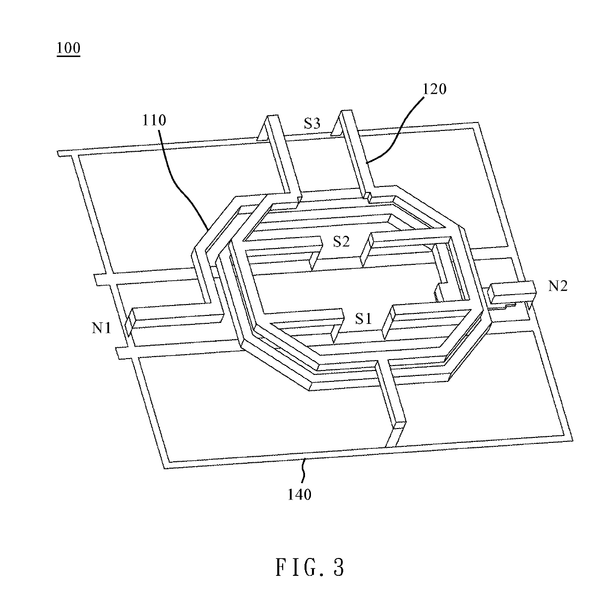
[0049]Referring to FIG. 3, FIG. 3 is schematic diagrams of a variable inductor according to an embodiment of the present disclosure. The variable inductor 100 has a primary conductor 110, a first secondary conductor 120, a first switch S1, a second switch S2 and a third switch S3, wherein the primary conductor 110 and the first secondary conductor 120 magnetically couple to each other to form a transformer structure. By controlling the first through third switches S1 through S3, the equivalent inductance of the first secondary conductor 120 and coupling factor are changed due to magnetic coupling theory of the transformer structure. The inductance value of the primary conductor 110 is changed as the equivalent inductance of the first secondary conductor 120 and coupling factor are changed. Therefore, the primary conductor 110, the first secondary conductor 120 and the first through third switches S1 through S3 can achieve the object of variable inductance.

[0050]In FIG. 3, the first ...


PUM

PropertyMeasurementUnit
currentaaaaaaaaaa
currentaaaaaaaaaa
inductanceaaaaaaaaaa

Abstract

A variable inductor which comprises a primary conductor, first and second secondary conductors and one or more switch. The primary conductor has a first node and a second node, wherein the first node is used to connect a first external component and the second node is used to connect a second external component. The first and second secondary conductors magnetically couple to the primary conductor. The one or more switch has two sides connected to the first or second secondary conductor, respectively. The first and second secondary conductors are formed a single-loop structure with two or more changeable current paths which are operated by the states of the one or more switch. An integrated circuit using the variable inductor is also introduced.

Description

FIELD OF THE INVENTION[0001]The present disclosure relates to a variable inductor and, more particularly, to a variable inductor which can be formed on an integrated circuit.BACKGROUND OF THE INVENTION[0002]Referring to FIG. 1A and FIG. 1B, FIG. 1A and FIG. 1B shows a conventional variable inductor. The conventional variable inductor 1000 has a primary conductor 1100 and a secondary conductor 1200, a switch 1300 and a current source 1400. The secondary conductor 1200 forms a loop on the outside of the primary conductor 1100. The switch 1300 couples in series with the secondary conductor 1200 and is turned on or off to make the loop close or open. The inductance of the conventional variable inductor 1000 is varied by closing and opening the loop with the switch 1300. The current source 1400 is also coupled in series with the secondary conductor 1200 and used to control the current flow in the secondary conductor 1200 to either increase or decrease the inductance.[0003]Referring to FI...

Claims


Application Information

Patent Timeline
Patent Type & Authority Patents(United States)
IPC IPC(8): H01F21/12H01L27/07H01L23/522
CPCH01L23/5227H01L27/0705H01F21/12H01F27/2804H01F2021/125H01F2027/2809
Inventor LIANG, CHIA-JENKUAN, YEN-CHENGCHIANG, CHING-WENYU, CHIEN-TE
Owner NAT CHUNG SHAN INST SCI & TECH
Why Eureka
Try Eureka