Leakage protective plug

a leakage protection and plug technology, applied in the field of plugs, can solve the problems of poor contact of supply circuits, failure of power leakage protection functions, and potential security risks that exist, and achieve the effect of reducing components, saving raw materials, and simplifying the structure of the tripping mechanism

Active Publication Date: 2020-02-18
FOSHAN SHUNDE DISTRICT XINHUIDA ELECTRONICS CO LTD
View PDF4 Cites 1 Cited by
  • Summary
  • Abstract
  • Description
  • Claims
  • Application Information

AI Technical Summary

Benefits of technology

[0029]Compared with the existing devices, the present invention simplify the structure of the tripping mechanism of the leakage protective plug, involves less components by providing a snap fitting mechanism in the pressing arm instead of a tripping plate and saves raw materials. It also achieves advantages including tripping function and leakage protection for plug. It has a simple and reliable tripping mechanism, and avoids technical problems including poor contact of supply circuit and failure of power leakage protecting functions due to un-complete tripping which are resulted from the deformation of the tripping plate caused by the movement of the tripping iron core and by other external forces. In addition, it extends service life for the leakage protective plug.

Problems solved by technology

However, the structure of such leakage protection plug as mentioned in the above patent application is complicated that potential security risks usually exist.
For example, during using, the deformation of the tripping plate, which is easily caused by the movement of the iron core during tripping or other external forces, results in technical problems including poor contact of supply circuit and failure of power leakage protecting functions due to un-complete tripping.
In addition, such leakage protection plug has a low safety coefficient.

Method used


Image

  • Leakage protective plug
  • Leakage protective plug
  • Leakage protective plug

Examples


Embodiment Construction

[0038]It should be understood that the terms such as “upward”, “downward”, “forward” and “rearward” as used herein, refer to position and orientation relationships in accordance with drawings and are not intended to limit the particular configuration and operation of the present invention. As such, it is intended that the foregoing be regarded as illustrative rather than limiting.

[0039]The present invention will be further explained below in detail with reference to figures and particular embodiments.

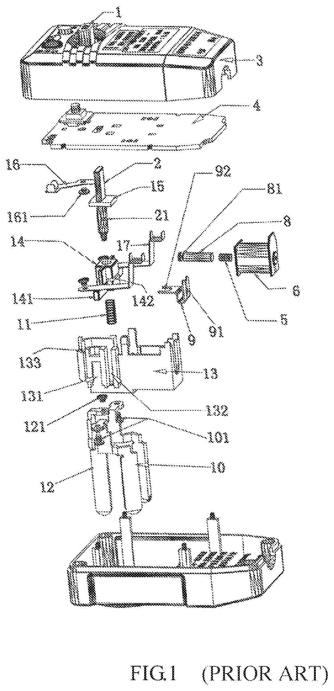
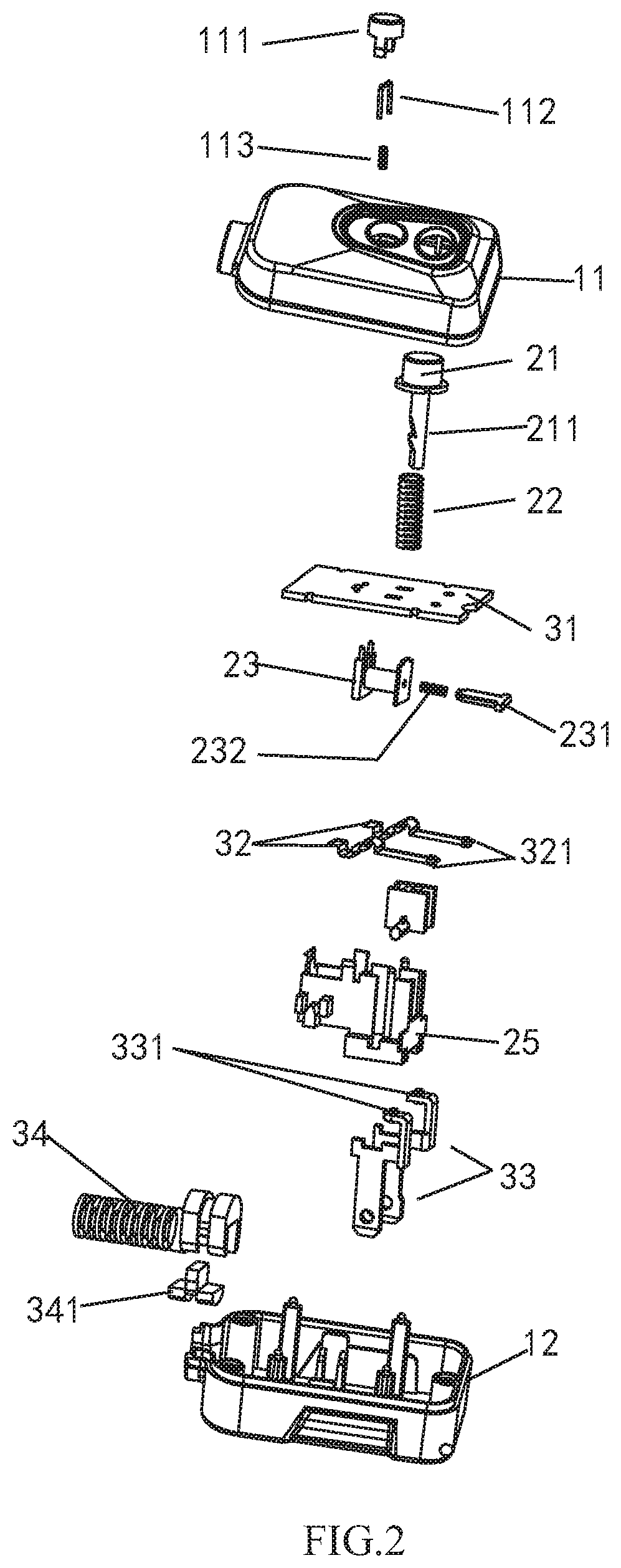
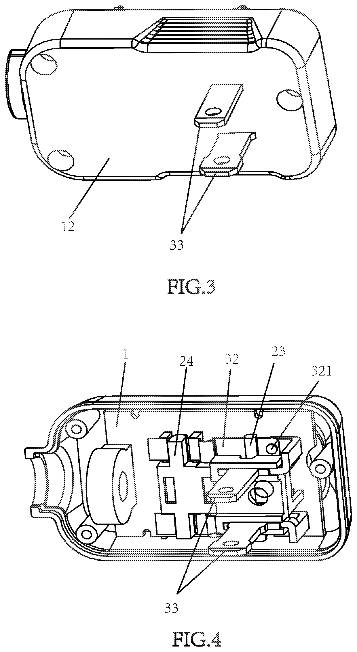
[0040]Referring to FIGS. 2-8:[0041]11. upper housing; 111. test button; 112. test bridge; 113. test spring; 12. lower housing;[0042]21. reset button; 211. retaining groove; 22. reset spring; 23. tripping coil; 231. iron core; 232. spring; 24. pressing arm; 241. retaining sliding groove; 242. snap fitting mechanism; 2421. snap fitting sliding groove; 2422. snap fitting part; 243. arms; 244. slope; 25. tripping bracket;[0043]31. circuit board; 32. movable contact springs for zero connecti...


PUM


Abstract

A leakage protective plug and a tripping mechanism thereof, comprising a housing, and a tripping mechanism and a conducting structure arranged within the housing, wherein the tripping mechanism comprises a restorable reset button, a tripping bracket, and a tripping coil and a pressing arm arranged in the tripping bracket, wherein the reset button is sleeved in the pressing arm in which a snap fitting mechanism is positioned such that the pressing arm and the reset button may be snapped together, and the pressing arm and the reset button may be disengaged under the control of the tripping coil. It has a simple and reliable structure, and avoids technical problems including poor contact of supply circuit and failure of power leakage protecting functions due to un-complete tripping which are resulted from the deformation of the tripping plate caused by the movement of the tripping iron core and by other external forces.

Description

CROSS REFERENCE TO RELATED APPLICATIONS[0001]This application claims priority from Chinese Utility Model Application No. 201621332892.6 and Chinese Patent Application No. 201611110384.8, both filed on Dec. 6, 2016, the entire contents of which are incorporated herein by reference.FIELD OF THE INVENTION[0002]The present invention relates to the field of plugs, more particularly to a leakage protective plug and a tripping mechanism thereof.BACKGROUND OF THE INVENTION[0003]In order to cut off the power in time, existing leakage protective plugs usually includes a tripping mechanism.[0004]FIG. 1 illustrates a utility model application No. 200820099570.0, titled as plug having electricity leakage protection function and previously filed by same applicant as the present invention. Therein, a tripping mechanism comprises a pressing bar 2, and a pressing arm 14 and a big reset spring 11 which are sleeved on the pressing bar 2, wherein the pressing arm 14 is upwardly and downwardly movable i...

Claims


Application Information

Patent Timeline
Patent Type & Authority Patents(United States)
IPC IPC(8): H01R13/648H01H50/32H01H50/20H01R24/28H01R13/713H01H50/02H01R24/68H01R103/00
CPCH01H50/326H01R24/28H01R13/713H01H50/021H01H50/20H01H2235/01H01R24/68H01R2103/00
Inventor LONG, HUANXIANGGUO, QI
Owner FOSHAN SHUNDE DISTRICT XINHUIDA ELECTRONICS CO LTD
Why Eureka
Try Eureka