Spherical bearing device and switch

a bearing device and switch technology, applied in the direction of electronic switching, shaft and bearings, pulse technique, etc., can solve the problems of increasing the number of components, difficult to obtain the above advantage, and difficulty in manufacturing, so as to achieve the freedom of shaft members and simple structure. , the effect of restricting the degree of freedom

Active Publication Date: 2020-04-21
PANASONIC INTELLECTUAL PROPERTY MANAGEMENT CO LTD
View PDF11 Cites 2 Cited by
  • Summary
  • Abstract
  • Description
  • Claims
  • Application Information

AI Technical Summary

Benefits of technology

[0006]In such a case, the requirement complicates the structure and increases the number of components, thereby causing difficulty in manufacturing, for example, like the spherical bearing device disclosed in Japanese Registered Utility Model No. 3107440. This makes it difficult to obtain the above advantage, i.e., simple structure and possible miniaturization.
[0007]The present disclosure, which is made in view of the above-mentioned problem of the conventional spherical bearing devices, aims to provide a spherical bearing device that can restrict a degree of freedom in movement of a shaft member with a simple structure without limiting the possibilities of miniaturization, and a switch including the same.
[0008]To achieve the above-mentioned aim, the spherical bearing device in accordance with the present disclosure includes a shaft member, a turnable body, and a bearing. The shaft member has a spherical body having a first engaging portion, and a shaft body disposed with an axis passing through a center of the spherical body. The turnable body has a second engaging portion. The second engaging portion is engaged with the first engaging portion in a first rotational direction about a first axis passing through the center of the spherical body, and allows the first engaging portion to rotate in a second rotational direction about a second axis intersecting with the first axis at the center. The bearing is provided with a first space and a second space, holds the shaft member so as to be spherically slidable, and allows the shaft body to move as the spherical body slides spherically. The first space accommodates the spherical body such that the spherical body is spherically slidable about the center of the spherical body, and the second space accommodates the turnable body of which the second engaging portion is engaged with the first engaging portion such that the turnable body is rotatable about a third axis intersecting with the first and second axes at the center.
[0010]Thus, a degree of freedom of the shaft member can be restricted with respect to a bearing with a simple structure, and therefore a small-sized spherical bearing device can be provided.

Problems solved by technology

In such a case, the requirement complicates the structure and increases the number of components, thereby causing difficulty in manufacturing, for example, like the spherical bearing device disclosed in Japanese Registered Utility Model No. 3107440.
This makes it difficult to obtain the above advantage, i.e., simple structure and possible miniaturization.

Method used


Image

  • Spherical bearing device and switch
  • Spherical bearing device and switch
  • Spherical bearing device and switch

Examples


first exemplary embodiment

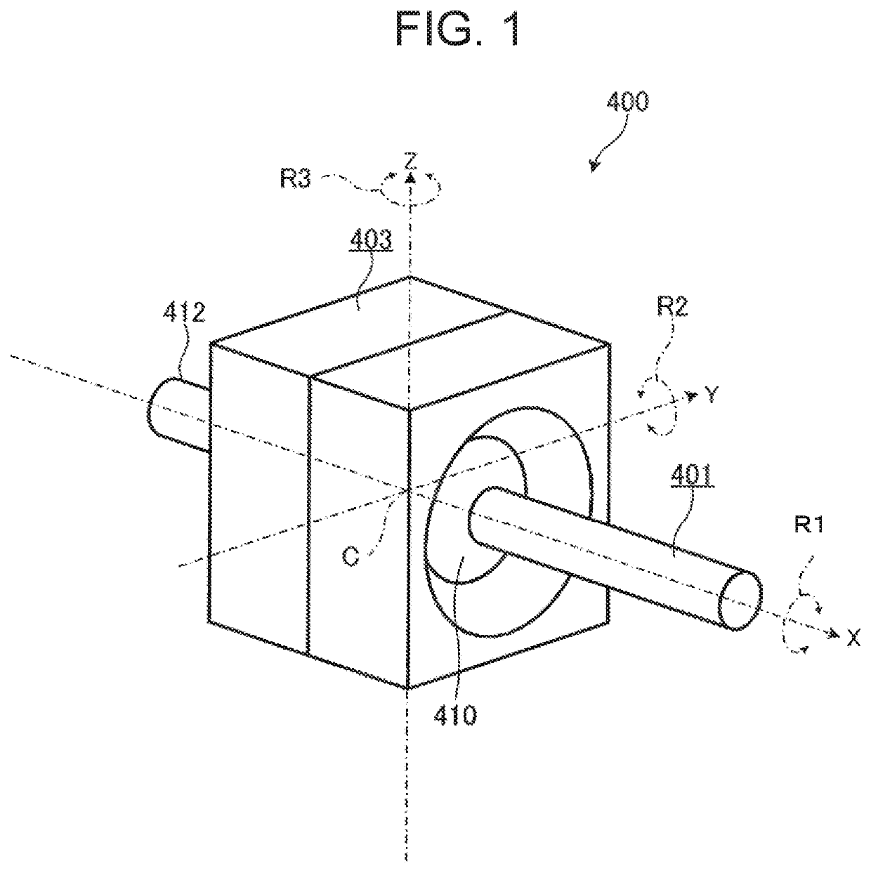
[0047]FIG. 1 is a perspective view showing appearance of a spherical bearing device in accordance with a first exemplary embodiment.

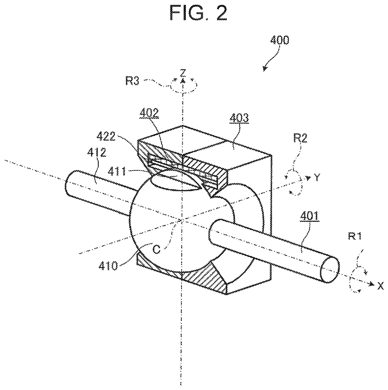
[0048]FIG. 2 is a perspective view of the spherical bearing device in which a bearing and a turnable body are cut out.

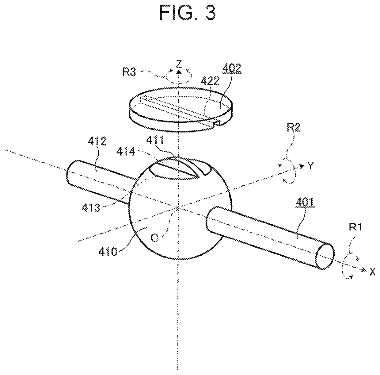
[0049]FIG. 3 is an exploded perspective view of a shaft member and the turnable body when the bearing is omitted.

[0050]As shown in these views, spherical bearing device 400 includes shaft member 401, turnable body 402, and bearing 403.

[0051]Shaft member 401 serves as a moving part that moves in the state where any one of three kinds of degrees of freedom is restricted with respect to bearing 403. Shaft member 401 includes spherical body 410 having first engaging portion 411 for restricting one degree of freedom in movement of shaft member 401, and shaft body 412 to be attached to spherical body 410. In the case of the present exemplary embodiment, shaft body 412 is disposed such that the center axis thereof passes through center C of sph...

second exemplary embodiment

[0063]Subsequently, switch 500 including spherical bearing device 400 will be described as a second exemplary embodiment. Note that, the same reference numerals are assigned to the same objects (portions), which have the same action and function, or the same shape, mechanism, and structure as in the first exemplary embodiment mentioned above, and the description thereof may be omitted. Further, in the following, a different point from the first exemplary embodiment will mainly be described, and description about the same contents may be omitted.

[0064]FIG. 5 is a perspective view of switch 500 in accordance with the second exemplary embodiment, in which the bearing and the turnable body are cut out.

[0065]Switch 500 is a device that outputs an operation signal indicating movement of shaft member 401 based on movement of shaft member 401 with respect to bearing 403 of spherical bearing device 400. Switch 500 includes spherical bearing device 400, sensor 404, board 405, and spacer 406.

[...

third exemplary embodiment

[0085]Next, as a third exemplary embodiment, a transmission mechanism, a lever mechanism, and a non-contact lever switch will specifically be described with reference to the drawings. Herein, the transmission mechanism is one embodiment of spherical bearing device 400, and is included in the lever mechanism and the non-contact lever switch.

[0086]Note that, the exemplary embodiment described below represents one application of the present disclosure.

[0087]Hereinafter, the third exemplary embodiment will be described with reference to FIGS. 16 to 28.

[0088]FIG. 16 is a view showing an installation example of the non-contact lever switch in accordance with the third exemplary embodiment. FIG. 17 is an exploded view of the non-contact lever switch and a control device in accordance with the third exemplary embodiment.

[0089]As shown in FIG. 16, non-contact lever switch 1 is installed in, for example, driver's seat of a car, and includes lever mechanisms 10 and 30 and control device 20. Le...


PUM


Abstract

A spherical bearing device includes a shaft member, a turnable body, and a bearing. The shaft member has a shaft body and a spherical body having a first engaging portion. The turnable body has a second engaging portion that is engaged with the first engaging portion in a first rotational direction about a first axis passing through a center of the spherical body, and allows other rotations. The bearing is provided with a first space and a second space. The first space accommodates the spherical body spherically slidably. The second space accommodates the turnable body such that the turnable body is turnable, and allows the shaft body to move.

Description

CROSS-REFERENCE TO RELATED APPLICATIONS[0001]This application is a continuation of the PCT International Application No. PCT / JP2016 / 004621 filed on Oct. 19, 2016, which claims the benefit of foreign priority of Japanese patent application No. 2015-235923 filed on Dec. 2, 2015, the contents all of which are incorporated herein by reference.BACKGROUND1. Technical Field[0002]The present disclosure relates to a spherical bearing device capable of restricting rotation about any one axis, and a switch including the spherical bearing device.2. Description of the Related Art[0003]The spherical bearing device allows a shaft member to freely move in an X-direction and a Y-direction perpendicular to the X-direction with respect to a bearing, and further allows the shaft member to rotate about a center axis of the shaft member. In addition, the spherical bearing device can also be miniaturized, advantageously.[0004]As such a spherical bearing device, the spherical bearing device described in Un...

Claims


Application Information

Patent Timeline
Patent Type & Authority Patents(United States)
IPC IPC(8): F16C11/06H03K17/97H01H25/04H01H89/00
CPCH03K17/97F16C11/0604F16C11/0614H01H25/04H01H2089/005Y10T403/32737H03K2217/96015H03K2217/94068F16C11/06
Inventor NISHINAKAMA, HIDEKI
Owner PANASONIC INTELLECTUAL PROPERTY MANAGEMENT CO LTD
Why Eureka
Try Eureka