Cooking device

a cooking device and heat exchange technology, applied in the field of cooking devices, can solve the problems of reducing cooling efficiency, reducing heat exchange efficiency, and requiring large and high-power cooling fans, and achieve the effect of reducing pressure loss and reducing overall height of cooking devices

Active Publication Date: 2020-05-05
PANASONIC INTELLECTUAL PROPERTY MANAGEMENT CO LTD
View PDF16 Cites 28 Cited by
  • Summary
  • Abstract
  • Description
  • Claims
  • Application Information

AI Technical Summary

Benefits of technology

[0005]In the above conventional cooking device, an air inlet is provided at the back of a water supply tank, and thus the water supply tank narrows a cooling air passage. This increases a pressure loss in the cooling air passage, which in turn decreases cooling efficiency. As a result, a large and high-power cooling fan is required.
[0006]In addition, to prevent deformation of the water supply tank made of resin by heat transferred from a heating chamber, a certain distance needs to be secured between the heating chamber and the water supply tank. This makes it difficult to design a cooking device shorter in overall height.
[0007]The present disclosure solves this disadvantage of the above prior art, and enables the use of a smaller and more inexpensive cooling fan. The present disclosure aims to offer a cooking device that is shorter in overall height.
[0009]The exemplary embodiment suppresses a pressure loss in the cooling air passage to cool the inside of the cooking device with a smaller and more inexpensive cooling fan. As a result, the overall height of the cooking device can be made shorter.

Problems solved by technology

This increases a pressure loss in the cooling air passage, which in turn decreases cooling efficiency.
As a result, a large and high-power cooling fan is required.
This makes it difficult to design a cooking device shorter in overall height.

Method used


Image

  • Cooking device
  • Cooking device
  • Cooking device

Examples


Embodiment Construction

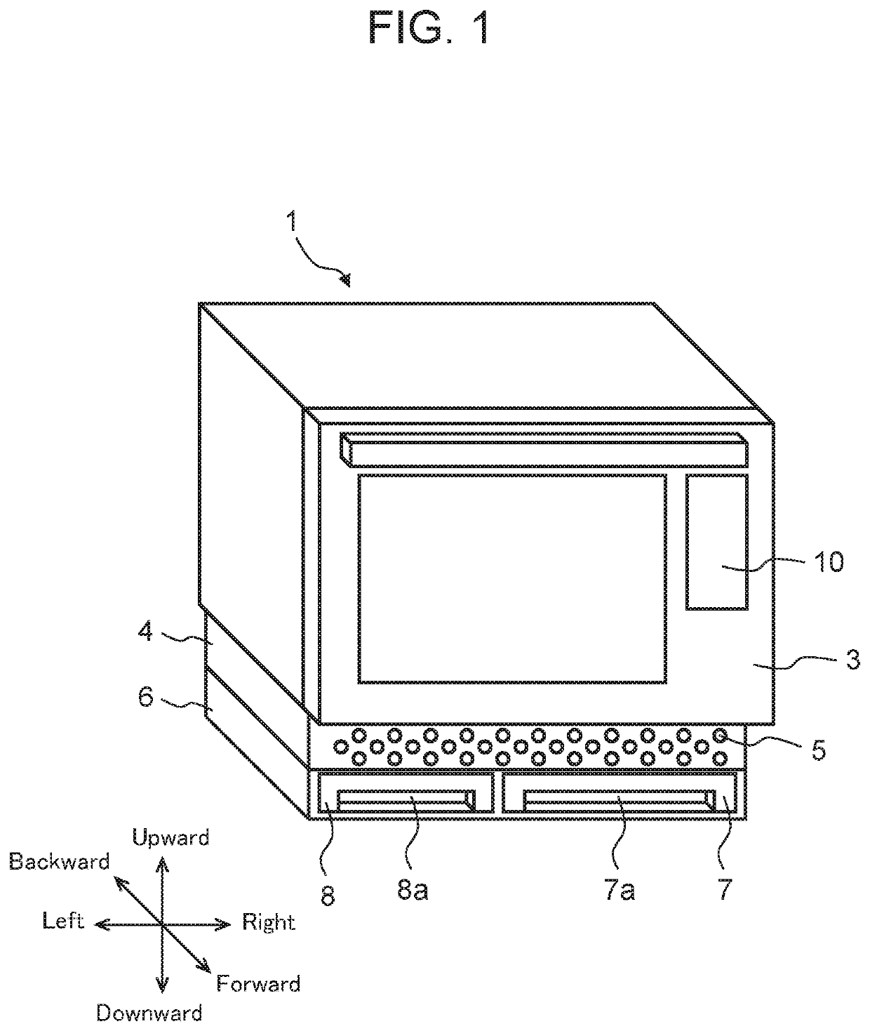
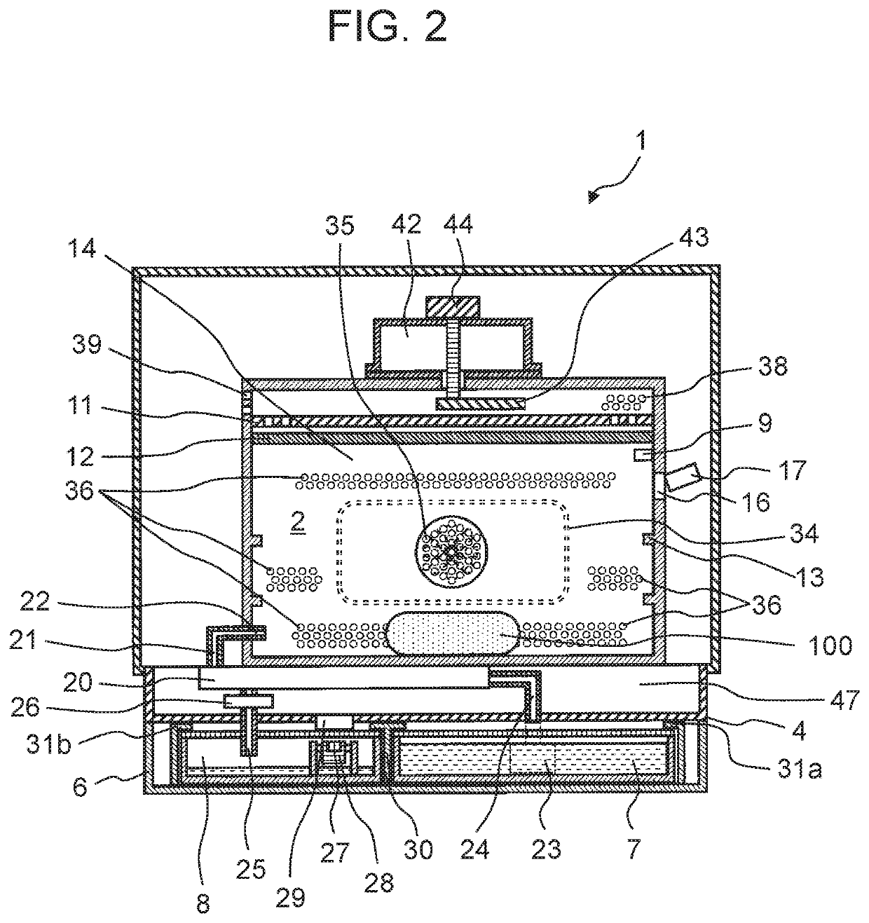
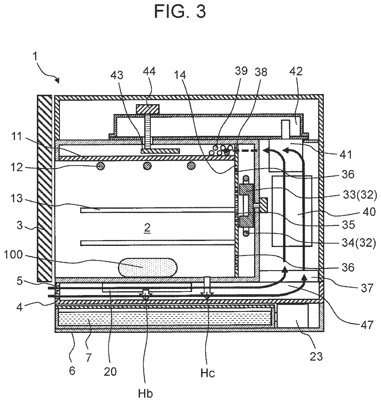
[0017]A cooking device in a first embodiment of the present disclosure includes a heating chamber with door for housing an object to be heated, a vapor generator for supplying vapor into the heating chamber, and a water storage tank. The cooking device in the embodiment further includes a cooling air passage which is provided between the heating chamber and the water storage tank and through which cooling air passes, and an air inlet provided on the door side and introducing cooling air into the cooling air passage.

[0018]This embodiment suppresses a pressure loss in the cooling air passage to cool the inside of the cooking device using a smaller and more inexpensive cooling fan. As a result, the overall height of the cooking device can be made shorter.

[0019]A cooking device in a second embodiment of the present disclosure includes a water supply tank in the water storage tank in the first embodiment. The water supply tank stores water to be supplied to the vapor generator.

[0020]This...


PUM


Abstract

Cooking device includes heating chamber with door for housing object to be heated, vapor generator for supplying vapor into heating chamber, and water storage tank. Cooking device further includes cooling air passage provided between heating chamber and water storage tank and allowing cooling air to pass therethrough, and air inlet provided to the side of door and introducing cooling air into cooling air passage. This enables cooling, using a smaller and more inexpensive cooling fan. As a result, cooking device is made shorter in overall height.

Description

[0001]This application is a 371 application of PCT / JP2016 / 000918 having an international filing date of Feb. 22, 2016, which claims priority to JP 2015-055650 filed Mar. 19, 2015, the entire contents of which are incorporated herein by reference.TECHNICAL FIELD[0002]The present disclosure relates to cooking devices using vapor for cooking.BACKGROUND ART[0003]A conventional cooking device of this type includes a water tank disposed in a recessed part on a bottom plate, and an air inlet provided at the back of the water tank and introducing cooling air (e.g., PTL1).CITATION LISTPatent Literature[0004]PTL1: Japanese Patent Unexamined Publication No. 2006-17404SUMMARY OF INVENTION[0005]In the above conventional cooking device, an air inlet is provided at the back of a water supply tank, and thus the water supply tank narrows a cooling air passage. This increases a pressure loss in the cooling air passage, which in turn decreases cooling efficiency. As a result, a large and high-power co...

Claims


Application Information

Patent Timeline
Patent Type & Authority Patents(United States)
IPC IPC(8): A47J36/00A47J27/04F24C15/32F24C15/00H05B6/80A47J36/02H05B6/64H05B6/00
CPCF24C15/327A47J27/04H05B6/6479F24C15/006H05B6/80A47J36/027A47J36/00H05B6/00F24C15/00
Inventor SHIBUYA, MASAKIKATAOKA, AKIRA
Owner PANASONIC INTELLECTUAL PROPERTY MANAGEMENT CO LTD
Why Eureka
Try Eureka