Shading correction device, reading device, image forming apparatus, shading correction method, and non-transitory recording medium
a reading device and shading correction technology, applied in the field of shading correction devices, can solve problems such as the increase of circuit size of attempts to accurately correct phase shifts
- Summary
- Abstract
- Description
- Claims
- Application Information
AI Technical Summary
Benefits of technology
Problems solved by technology
Method used
Image


Examples
first embodiment
[0043]the present invention will be described.
[0044]In the first embodiment described below, a shading correction device is applied to a reading device for better understanding of a form of use of the shading correction device. The reading device is a device that includes optical lenses and an image sensor and performs processes such as image processing on a signal read from a reading target by the image sensor (i.e., a read signal or a read image).
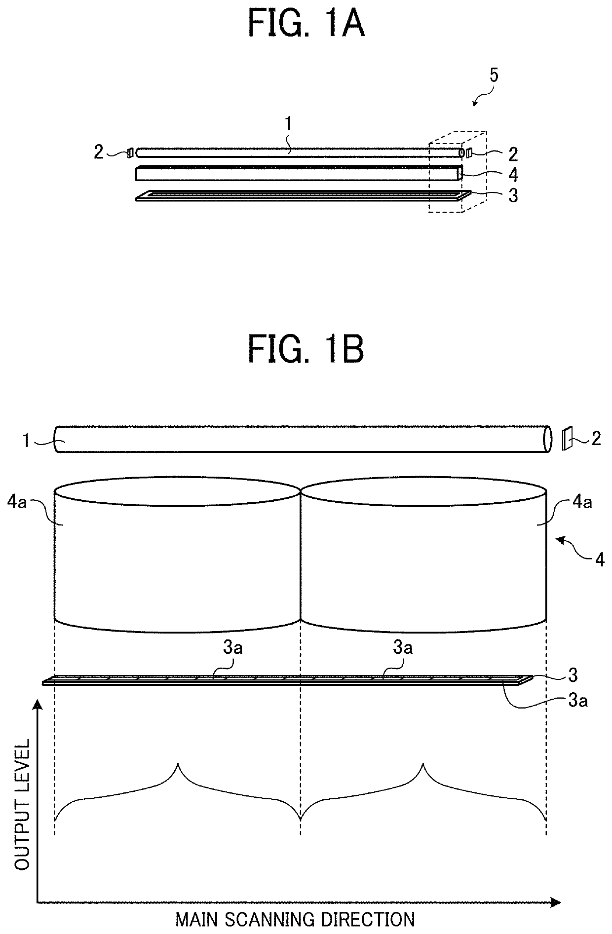
[0045]FIGS. 1A and 1B are diagrams illustrating an exemplary configuration of a reading device of the first embodiment. FIGS. 1A and 1B illustrate an exemplary configuration of a reading module 5 an example of the reading device. The reading module 5 is configured as a contact image sensor (CIS) that reads the image without magnification. FIG. 1A is an exploded perspective view of the reading module 5. FIG. 1B is an enlarged view of a part of the reading module 5 indicated by broken lines in FIG. 1A. FIG. 1B further illustrates an example...
second embodiment
[0117]the present invention will be described.
[0118]A description will be given of an exemplary configuration of an image forming apparatus according to the second embodiment. The following description will be given of a configuration of a multifunction peripheral (MFP) as an example of an image forming apparatus including an image reading device and an image forming device.
[0119]FIG. 20 is a diagram illustrating an exemplary general arrangement of an MFP 200 according to the second embodiment. FIG. 21 is a diagram illustrating an example of an automatic document feeder (ADF) included in the MFP 200. FIGS. 20 and 21 illustrate the MFP 200 and the ADF, respectively, as viewed with an external protection cover of the MFP 200 removed therefrom for better understanding of the internal configuration of the MFP 200. FIG. 22 is a diagram illustrating an exemplary configuration of control blocks of the MFP 200.
[0120]The MFP 200 illustrated in FIG. 20 includes an image reading device 10, a s...
PUM
 Abstract
Description
Claims
Application Information