

Embedded antenna and related MIMO system
a technology of embedded antennas and mimo systems, applied in the direction of resonant antennas, elongated active element feeds, transmission, etc., can solve the problems of low antenna efficiency, low gain, and jeopardize certification standards, and achieve the effect of improving energy conservation and small form factor
- Summary
- Abstract
- Description
- Claims
- Application Information
AI Technical Summary
Benefits of technology
Problems solved by technology
Method used
Image

Examples
first illustrated embodiment
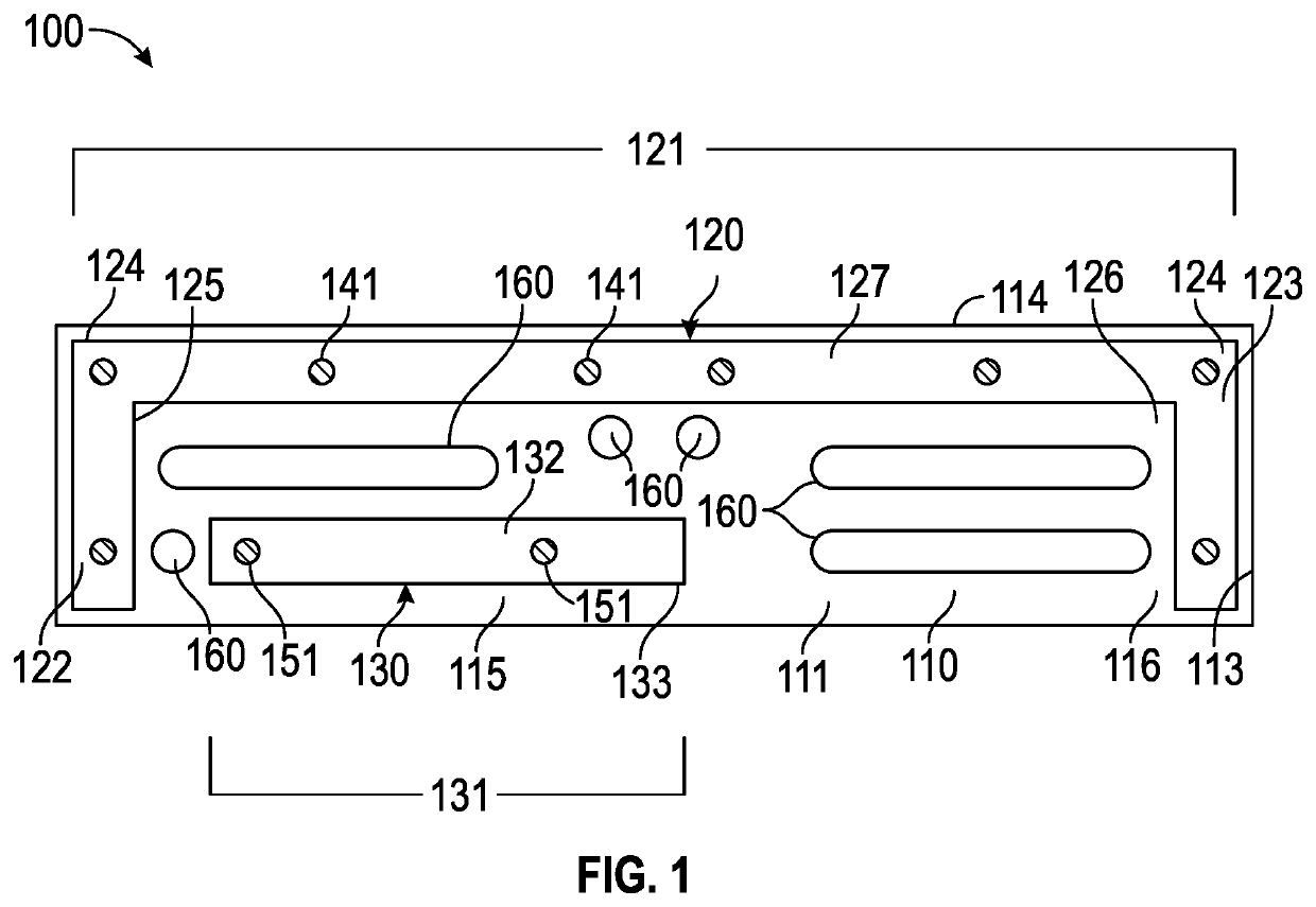
[0047]FIG. 1 shows a top view of an embedded antenna (100) in accordance with a first illustrated embodiment. The embedded antenna comprises a substrate (110) having a first surface (111) and a second surface (not shown) opposite the first surface. Disposed on the first surface is a first antenna radiator (120) and a second antenna radiator (130). The first surface further comprises one or more apertures (160) which are disposed through the substrate to the second surface, thereby allowing air to occupy portions of the substrate for lowering the dielectric constant to improve antenna performance. The one or more apertures may comprise round holes, oblong slots, or other shapes. Apertures disposed between the first and second antenna radiators have a even greater effect of concentrating an electromagnetic field between the first and second antenna radiators.
[0048]The first antenna radiator (120) comprises a first length (121) disposed along a major side (114) of the substrate (110). ...
second illustrated embodiment
[0060]FIG. 7A shows a top view of an embedded antenna (300) integrated with a mounting circuit board (370) in accordance with a second illustrated embodiment. The embedded antenna comprises a substrate (310) having a first antenna radiator (320) and second antenna radiator (330) disposed on a first surface (311). A second surface (not shown) opposite the first surface is coupled to the mounting circuit board. The mounting circuit board comprises a clearance zone (371) and a ground plane (372) wherein the clearance zone is disposed between the ground plane and a surface of the mounting circuit board coupled to the embedded antenna. The clearance zone includes a positive feed (373) configured to couple with a positive mounting pad (134, FIG. 5A) of the embedded antenna, and a negative feed (374) configured to couple with a negative mounting pad (128, FIG. 4A) of the embedded antenna. One with skill in the art will appreciate that the positive feed and negative feed are in an orthogona...
third illustrated embodiment
[0062]FIG. 8 shows a top view of a MIMO antenna system (400) in accordance with a third illustrated embodiment. The MIMO antenna system comprises system substrate (480) having a center portion (482) and a perimeter (481) surrounding the center portion. The center portion comprises a ground plane (472) and the perimeter comprises a clearance zone (472) in addition to a plurality of embedded antennas (484). The system substrate comprises a plurality of sides (483) such that at each of the plurality of sides is a mirrored antenna pair (486) of embedded antennas. Each of the plurality embedded antennas comprises a first antenna radiator (420) and a second antenna radiator (430). Extending from each of the plurality of embedded antennas towards the ground plane is a positive feed (473) and a negative feed (474).
[0063]As shown, the mirrored antenna pairs (486) comprise two embedded antennas such that the second antenna radiator (430) of each embedded antenna is positioned closest to a nea...
PUM
 Abstract
Description
Claims
Application Information