Image processing apparatus, image pickup apparatus, and control method of image processing apparatus

a technology of image processing and image pickup, which is applied in the direction of color television details, television system details, television systems, etc., can solve the problems of difficult application of techniques and temporary disappearance of targeted objects, and achieve the effect of preventing the loss of an image pickup opportunity

Active Publication Date: 2022-11-22
CANON KK
View PDF3 Cites 3 Cited by
  • Summary
  • Abstract
  • Description
  • Claims
  • Application Information

AI Technical Summary

Benefits of technology

[0005]The present invention provides an image processing apparatus, an image pickup apparatus, and a control method of an image processing apparatus each of which can easily recapture an object that is lost from an image pickup angle of view and can prevent a loss of an image pickup opportunity.

Problems solved by technology

However, when the object is lost from the image pickup angle of view and is necessary to be recaptured, the targeted object temporarily disappears.
Therefore, it is difficult to apply techniques disclosed in JP 2004-8323 and JP Patent No. 5828070.

Method used


Image

  • Image processing apparatus, image pickup apparatus, and control method of image processing apparatus
  • Image processing apparatus, image pickup apparatus, and control method of image processing apparatus
  • Image processing apparatus, image pickup apparatus, and control method of image processing apparatus

Examples


first embodiment

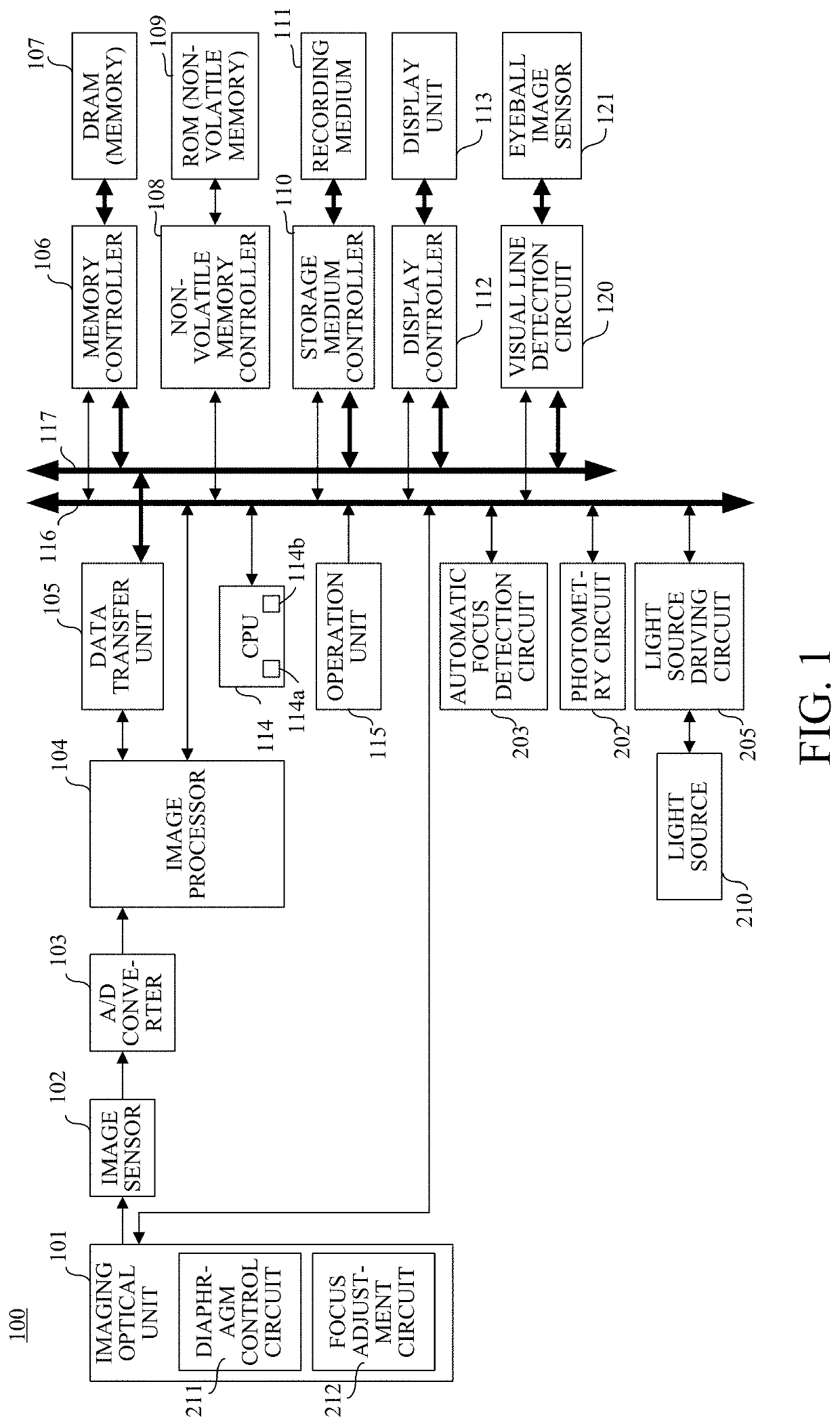
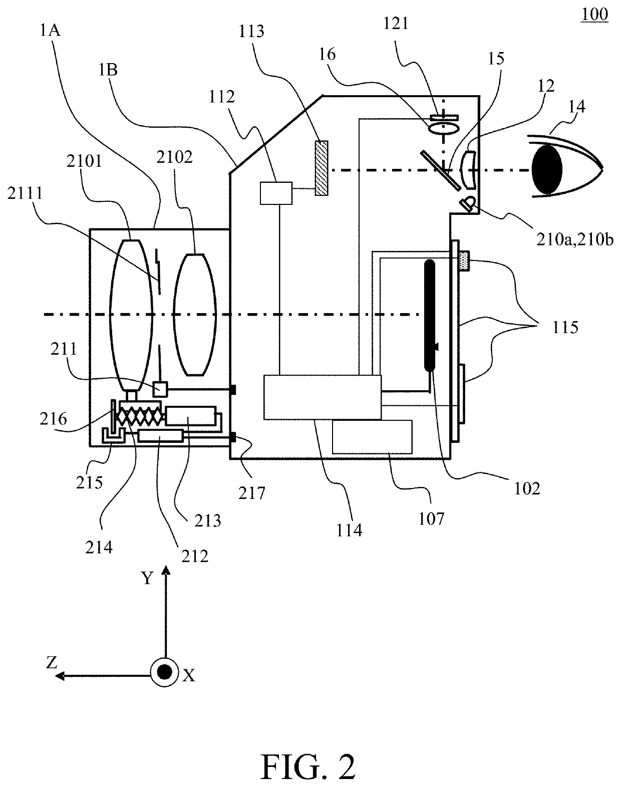
[0034]First, a description will be given of an image pickup apparatus (image processing apparatus) according to a first embodiment of the present invention with reference to FIGS. 1 and 2. FIG. 1 is a block diagram illustrating a digital camera 100 as an image pickup apparatus. FIG. 2 is a sectional view illustrating the digital camera 100. In FIG. 1 and FIG. 2, corresponding elements are represented by same reference numerals.

[0035]In FIG. 1, the imaging optical unit 101 includes an optical system as an image pickup optical system that includes a plurality of lens units having a focus lens and an image stabilization lens, a diaphragm, and the like. The imaging optical unit 101 includes a diaphragm control circuit 211 and a focus adjustment circuit 212. At a time of image pickup, the imaging optical unit 101 adjusts focus with the focus adjustment circuit 212, adjusts an exposure with the diaphragm control circuit 211, performs image stabilization, etc., and forms an optical image o...

second embodiment

[0064]Next, a description will be given of a second embodiment of the present invention with reference to FIGS. 8 and 10A to 10C. FIG. 8 is a flowchart illustrating a control method according to this embodiment. FIGS. 10A to 10C are schematic diagrams each illustrating a display screen of the display unit 113 according to this embodiment. Configurations of a digital camera according to this embodiment are the same as those of the digital camera 100 described in the first embodiment, and thus the description thereof will be omitted.

[0065]First, in step S801, the CPU 114 determines whether or not the image pickup assist button of the operation unit 115 is pressed and the image pickup assist operation (image pickup assist control) start instruction is input. When the image pickup assist operation start instruction is not input, step S801 is repeated. On the other hand, when the image pickup assist operation start instruction is input, the process proceeds to step S802. The CPU 114 meas...

third embodiment

[0071]Next, a description will be given of a third embodiment of the present invention with reference to FIGS. 9 and 10A to 10C. FIG. 9 is a flowchart illustrating a control method according to this embodiment. Each of FIGS. 10A to 10C is a schematic diagram illustrating a display screen of the display unit 113 according to this embodiment. Configurations of a digital camera according to this embodiment is the same as those of the digital camera 100 described in the first embodiment, and thus the description thereof will be omitted. The flowchart of FIG. 9 includes the same processing as that in the flowchart of FIG. 8 described in the second embodiment, and thus a description of the same processing will be omitted.

[0072]Step S901 is the same as step S801 in FIG. 8. After start of image pickup assist operation is determined in step S901, the process proceeds to step S902. In step S902, the CPU 114 starts measuring a time it takes for an angle of view frame 1000 at a focal length of ...


PUM


Abstract

An image processing apparatus includes a display unit configured to display an image captured via an optical system, an estimation unit configured to estimate a gazing point position of a user on a display unit, and a control unit configured to change a zoom position of an image displayed on the display unit. When start is instructed of image pickup assist control, the control unit zooms out the image displayed on the display unit from a first zoom position to a second zoom position on more wide-angle side than the first zoom position. When stop is instructed of the image pickup assist control, the control unit zooms in on a zoom-out image from the second zoom position to a third zoom position on more telephoto side than the second zoom position, based on the gazing point position estimated by the estimation unit.

Description

BACKGROUND OF THE INVENTIONField of the Invention[0001]The present invention relates to an image pickup apparatus having an image pickup assist function for recapture an object that is lost from an image pickup angle of view.Description of the Related Art[0002]Conventionally, an image pickup apparatus is known that has an image pickup assist function making it easier to recapture an object that is lost from a narrow image pickup angle of view, such as that in a telephoto image pickup. For example, when a user starts the image pickup assist via an operation member in order to recapture an object that is lost from the image pickup angle of view, the object is captured by automatically zooming out to a wide-angle direction, and thereafter when the user cancels the image pickup assist, zoom in is automatically performed to a telephoto direction (framing assist).[0003]Japanese Patent Laid-Open No. (“JP”) 2004-8323 discloses a technique for recognizing an object intended by a user based o...

Claims


Application Information

Patent Timeline
Patent Type & Authority Patents(United States)
IPC IPC(8): H04N5/232H04N5/225
CPCH04N5/23219H04N5/2258H04N5/23222H04N5/23293H04N5/23296H04N5/272H04N23/45H04N23/64H04N23/611H04N23/634H04N23/632H04N23/69H04N23/63
Inventor EBATA, YUYAYAGUCHI, HIROYUKI
Owner CANON KK
Why Eureka
Try Eureka