Separating device for separating fluids from solids and use thereof

a separation device and solid separation technology, applied in the field of separation devices, can solve the problems of high cost, unsatisfactory dewatering capacity of the above-mentioned separators, and insufficient fresh water supply

Inactive Publication Date: 2004-02-26
RUDOLF BISCHOF
View PDF5 Cites 6 Cited by
  • Summary
  • Abstract
  • Description
  • Claims
  • Application Information

AI Technical Summary

Problems solved by technology

The disadvantage in separators of the aforementioned kind known hitherto is that fresh water is needed in most cases to flush the press water discharge zone to prevent deposits and encrustations.
The dewatering capacity of the separators of the aforementioned kind known hitherto is often unsatisfactory, i.e. the ejected remaining stock is still relatively moist, necessitating cost-intensive disposal.
Due to the force needed for ejection, the already expressed sol

Method used


Image

  • Separating device for separating fluids from solids and use thereof
  • Separating device for separating fluids from solids and use thereof
  • Separating device for separating fluids from solids and use thereof

Examples


Embodiment Construction

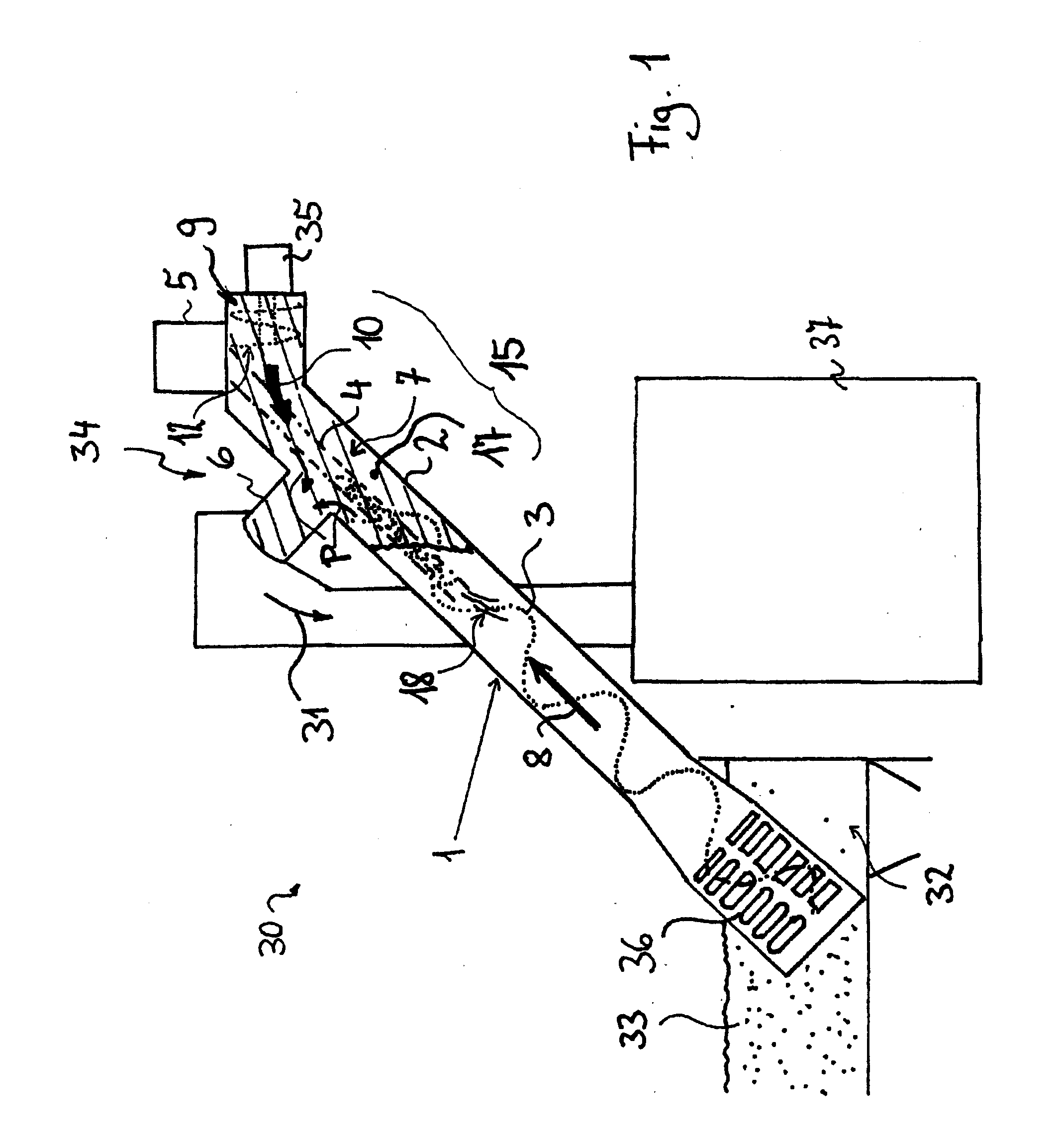
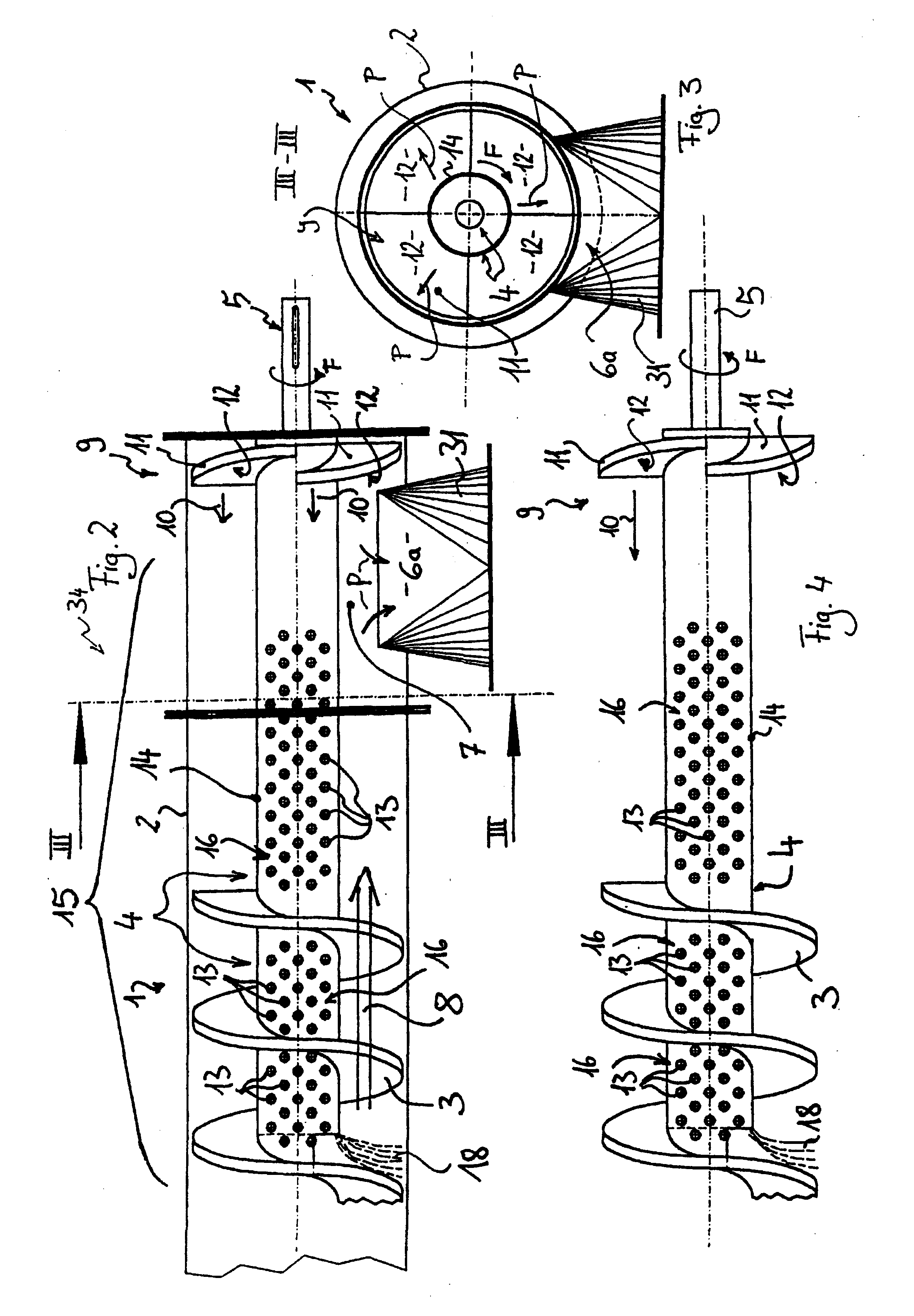
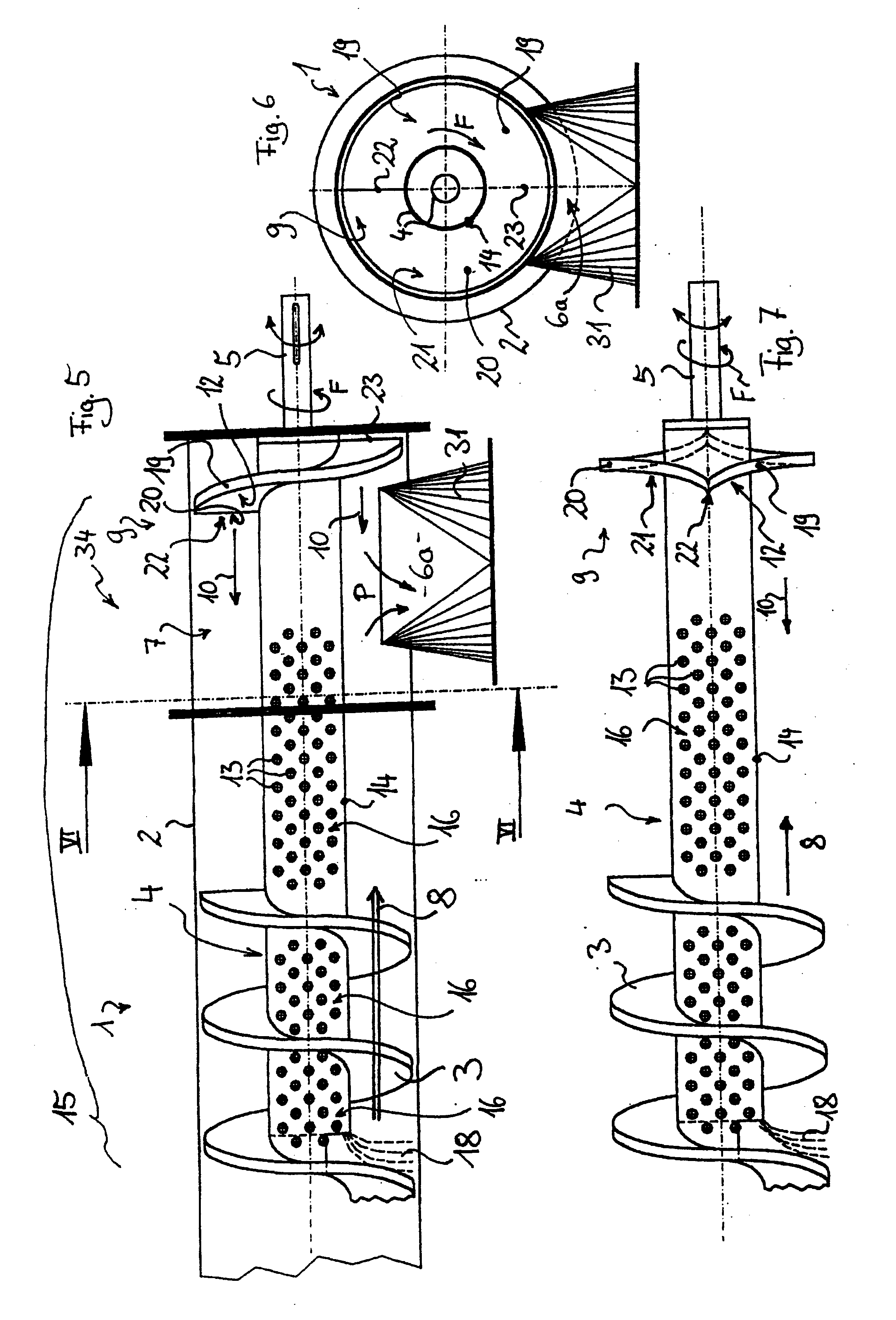
[0034] FIGS. 1, 2, 3, 5 and 6 each show fully or in part a screw feeder 1 as part of a slurry separator 30 for optimum separation of solids 31 and liquid 18, 32 of a slurry 33. The separator 30 may be used to extract e.g. solids from waste water. As regards the general configuration of separators 30 provided with screw feeders 1 express reference is made to DE 42 11 606 C1. The novelty as described presently is mainly directed at means for implementing dewatering of the extracted solids, i.e. more particularly dewatering solids as filtered or screened from waste water. For this purpose the discharge zone 34 as shown separately in FIGS. 2 and 5, i.e. the end portion of the feed section of the separator 30, is configured as the separator for separating the liquid from the solids.

[0035] The screw feeder 1 comprises a housing 2, a helical flight 3 and a shaft 4. The shaft 4 is connected to the gearing of a drive unit 5 for rotating the helical flight 3.

[0036] Referring now to FIG. 1 the...


PUM

PropertyMeasurementUnit
Pressureaaaaaaaaaa
Heightaaaaaaaaaa

Abstract

The invention relates to a separating device for separating fluids (18) from solids (31), in particular for the separation of fluids (18) from material previously isolated from a solid-fluid mixture (33), comprising:-a screw transport device (1), provided with a housing (2), a shaft (4) and a conveying helix (3), a compacting zone (15) wherein the solid conveyed by the screw transport device (1) is compressed to express the fluid, a sieve area (16), in particular on the compacting zone (15) and a solids discharge section (7) where the expressed solids are led away from the rotating axis of the screw transport device (1). According to the invention, the drainage effect may be improved, whereby a counter transport device (9) is provided for the transport of solids in a direction (10), opposed to at least one direction component of the transport device (8) on the screw transport (1), in such a way that solids in the compacting zone (15) and/or in the solids discharge section (7) are put under pressure by the counter transporting (10), in order to increase the expression force for the expression of fluids and the discharge force (P) for the discharge of expressed solids from the separating device. According to the invention, the drainage effect may be alternatively, or additionally improved, whereby the sieve surface (16) is formed at least partly on the shaft (4). Further, a preferred application of the above separating device in a mechanical effluent treatment is disclosed.

Description

[0001] The invention relates to a separator for separating liquid from solids, more particularly for separating liquid from stock previously extracted from a slurry, comprising:[0002] a) a screw feeder provided with a housing, shaft and helical flight,[0003] b) a compacting zone in which solids conveyed by the screw feeder are compacted to express the liquid,[0004] c) a screen, more particularly at the compacting zone and[0005] d) a solids discharge section at which expressed solids are removed from the axis of rotation of the screw feeder.[0006] In addition, the invention relates to use of such a separator.[0007] The separator in accordance with the invention is mainly intended for application in the field of mechanical effluent treatment in many municipal sewage treatment plants of which screening or raking systems are already in use integrated with a press zone, also termed dewatering zone. These machines separate solids from slurries, convey the stock by means of a screw feeder ...

Claims


Application Information

Patent Timeline
IPC IPC(8): B01D21/24B30B9/12
CPCB01D21/2405B01D21/2461B30B9/12B30B9/121B30B9/128
Inventor BISCHOF, RUDOLF
Owner RUDOLF BISCHOF
Why Eureka
Try Eureka