Concrete block mold with moveable liner

a technology of concrete block and liner, which is applied in the direction of manufacturing tools, applications, gearing, etc., can solve the problems of cam mechanism, insufficient spring energy storage, and potential insufficient pattern or texture to retract sidewalls, etc., and achieves the effect of reducing the number of molds

Active Publication Date: 2005-02-03
NESS INVENTIONS
View PDF11 Cites 46 Cited by
  • Summary
  • Abstract
  • Description
  • Claims
  • Application Information

AI Technical Summary

Problems solved by technology

However, because of the way finished blocks are vertically ejected from the mold, any such pattern or, texture would be stripped from the side walls unless they are moved away from the mold interior prior to the block being ejected.
However, this technique applies an “active” force to the sidewall only when the sidewall is being moved inward and relies on the energy stored in the spring to move the sidewall outward.
The energy stored in the spring may potentially be insufficient to retract the sidewall if the sidewall sticks to the concrete.
Additionally, the cam mechanism can potentially be difficult to utilize within the limited confines of a concrete block machine.
Thus, during compression of the concrete by the head shoe assembly, an enormous amount of pressure is exerted directly on the piston via the piston shaft.
Additionally, the direct pressure on the piston shaft can potentially cause increased wear and shorten the expected life of the piston.

Method used


Image

  • Concrete block mold with moveable liner
  • Concrete block mold with moveable liner
  • Concrete block mold with moveable liner

Examples


Embodiment Construction

[0034] In the following Detailed Description, reference is made to the accompanying drawings which form a part hereof, and in which is shown by way of illustration specific embodiments in which the invention may be practiced. In this regard, directional terminology, such as “top,”“bottom,”“front,”“back,”“leading,”“trailing,” etc., is used with reference to the orientation of the Figure(s) being described. Because components of embodiments of the present invention can be positioned in a number of different orientations, the directional terminology is used for purposes of illustration and is in no way limiting. It is to be understood that other embodiments may be utilized and structural or logical changes may be made without departing from the scope of the present invention. The following detailed description, therefore, is not to be taken in a limiting sense, and the scope of the present invention is defined by the appended claims.

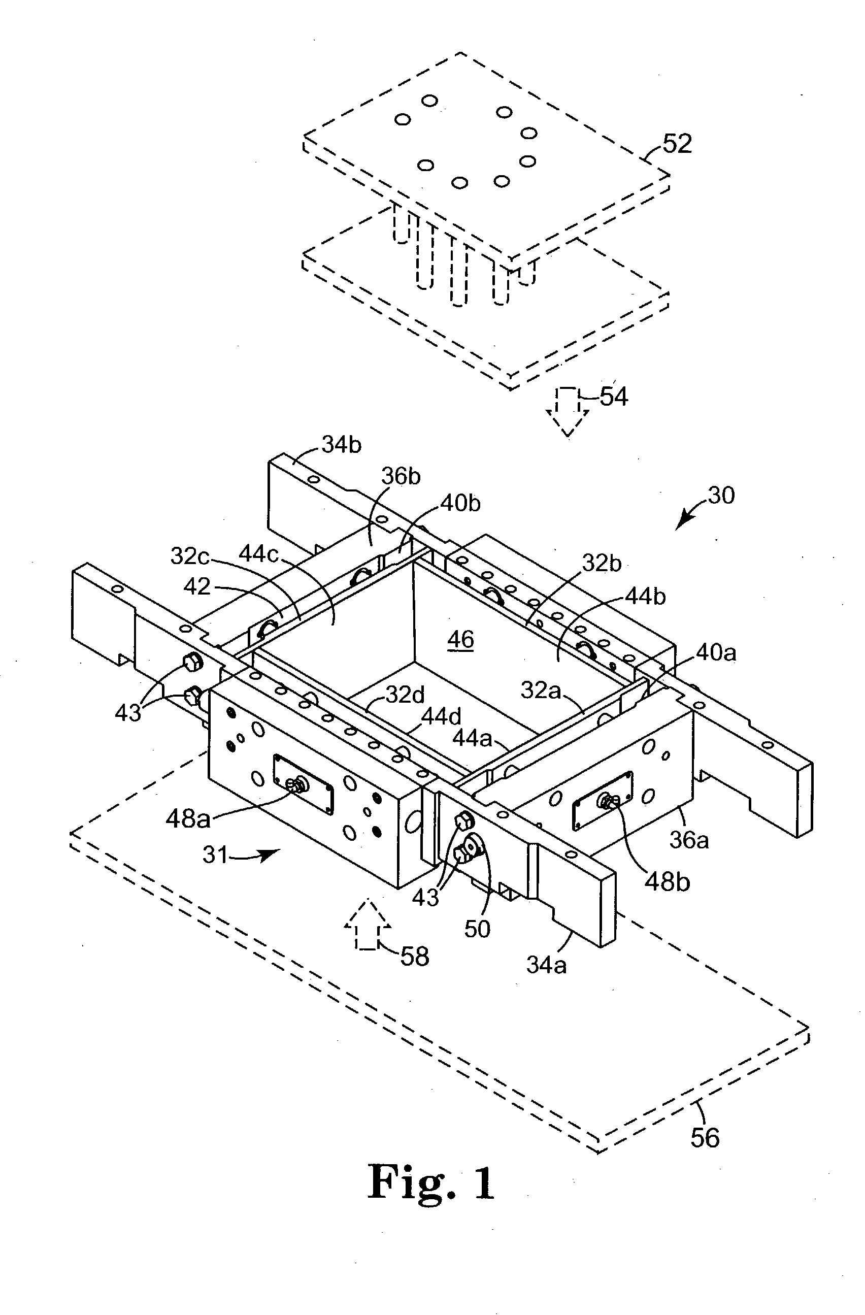
[0035]FIG. 1A is a perspective view of one exemplary...


PUM

PropertyMeasurementUnit
zero degree angleaaaaaaaaaa

Abstract

One aspect of the present invention provides a mold assembly for manufacturing concrete blocks that is adapted for use in a concrete block machine. The mold assembly comprises a plurality of liner plates and a gear drive assembly. Each liner plate has a major surface and the liner plates are configured such that the major surfaces form a mold cavity, wherein at least one of the liner plates is moveable. The gear drive assembly is selectively coupled to the at least one moveable liner plate and is configured to move the at least one moveable liner plate in a first direction toward an interior of the mold cavity by applying a force in a second direction different from the first direction, and to move the liner plate in a direction away from the interior of the mold cavity by applying a force in a direction opposite the second direction.

Description

THE FIELD OF THE INVENTION [0001] The present invention relates to concrete block molds, and more particularly to a concrete block mold adapted for use with a concrete block machine and having at least one moveable liner. BACKGROUND OF THE INVENTION [0002] Concrete blocks, also referred to as concrete masonry units (CMU's), are typically manufactured by forming them into various shapes using a concrete block machine employing a mold frame assembled so as to form a mold box. A mold cavity having a negative of a desired shape of the block to be formed is provided within the mold box. A support board, or pallet, is moved via a conveyor system onto a pallet table. The pallet table is moved upward until the pallet contacts and forms a bottom of the mold box. The cavity is then filled with concrete by a moveable feedbox drawer. [0003] As soon as the mold is filled with concrete, the feedbox drawer is moved back to a storage position and a plunger, or head shoe assembly, descends to form a...

Claims


Application Information

Patent Timeline
Patent Type & Authority Applications(United States)
IPC IPC(8): B28B7/00B28B7/24B28B7/34B28B7/36B28B15/00F15B15/02F15B15/08F16H25/18
CPCB28B7/0041B28B7/0064B28B7/24B28B7/348F16H25/183B28B7/366B28B15/005F15B15/02F15B15/065B28B7/364
Inventor NESS, JOHN T.
Owner NESS INVENTIONS
Why Eureka
Try Eureka