Change-speed control system for utility vehicle having stepless change-speed apparatus for speed-changing engine output and transmitting the speed-changed output to traveling unit

a control system and utility vehicle technology, applied in the direction of fluid gearings, machines/engines, gearings, etc., can solve the problem of affecting the start of the vehicl

Active Publication Date: 2005-02-17
KUBOTA LTD
View PDF1 Cites 8 Cited by
  • Summary
  • Abstract
  • Description
  • Claims
  • Application Information

AI Technical Summary

Benefits of technology

[0006] In view of the above-described state of the art, a primary object of the invention is to provide a change-speed control system capable of avoiding the above-described trouble at t

Problems solved by technology

So that, due to this driving load, the start of the vehicle can be hi

Method used


Image

  • Change-speed control system for utility vehicle having stepless change-speed apparatus for speed-changing engine output and transmitting the speed-changed output to traveling unit
  • Change-speed control system for utility vehicle having stepless change-speed apparatus for speed-changing engine output and transmitting the speed-changed output to traveling unit
  • Change-speed control system for utility vehicle having stepless change-speed apparatus for speed-changing engine output and transmitting the speed-changed output to traveling unit

Examples


Embodiment Construction

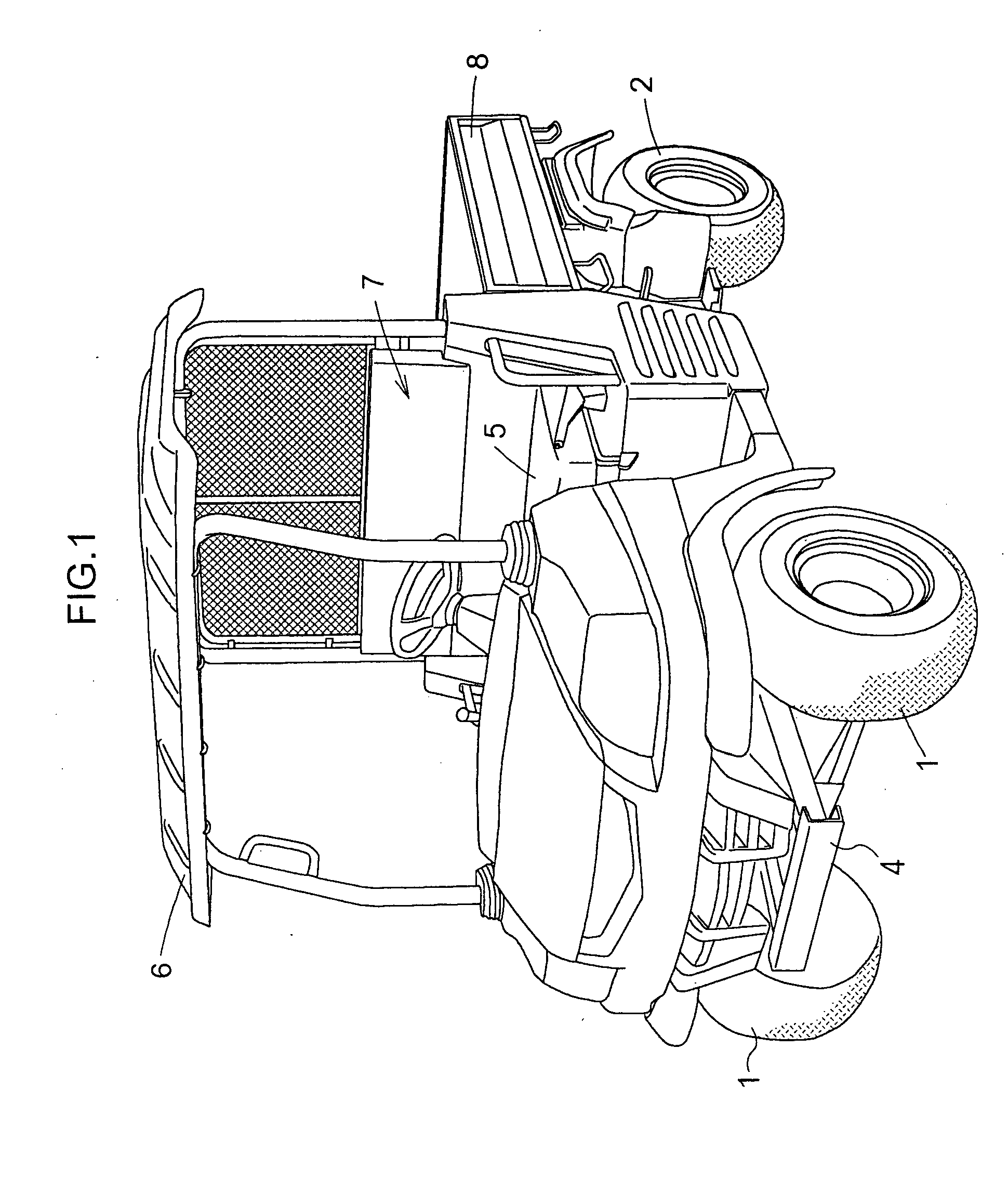
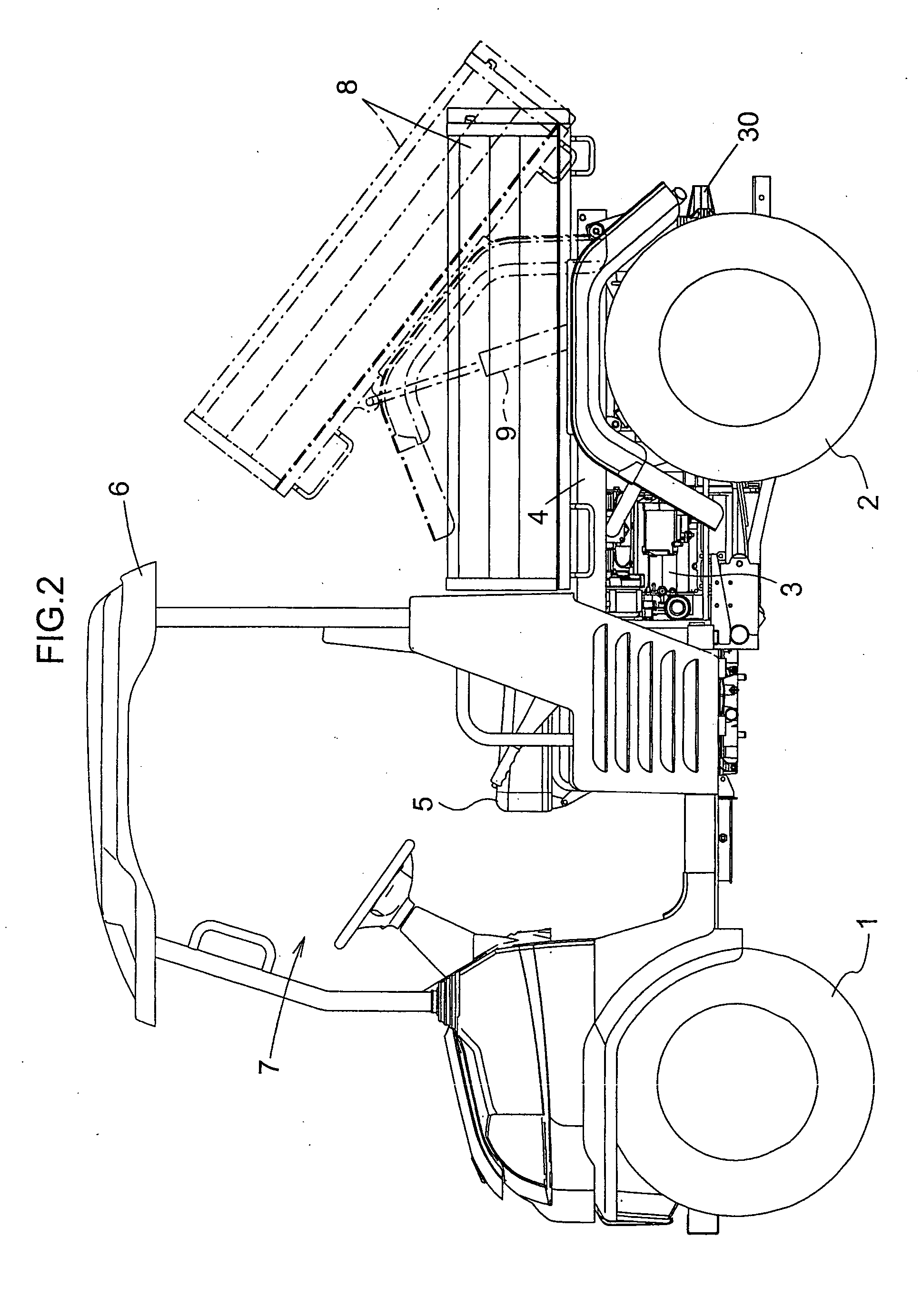
[0025] As shown in FIG. 1, FIG. 2 and FIG. 3, a utility vehicle includes a vehicle chassis 4 supported on the ground by a pair of left and right steerable tired front wheels 1 and a pair of left and right tired rear wheels 2. The chassis 4 mounts, at its front portion and between the front and rear wheels, an engine 3 for driving the front and rear wheels 1, 2. The chassis 4 further mounts, at its front portion, a driver's cabin 7 including a seat 5 and a sunshade 6. The chassis 4 mounts, at its rear portion, a load carrier 8, which is vertically pivotable by a dump cylinder 9 about an axis located rearwardly of the carrier 8 and extending transversely of the vehicle body.

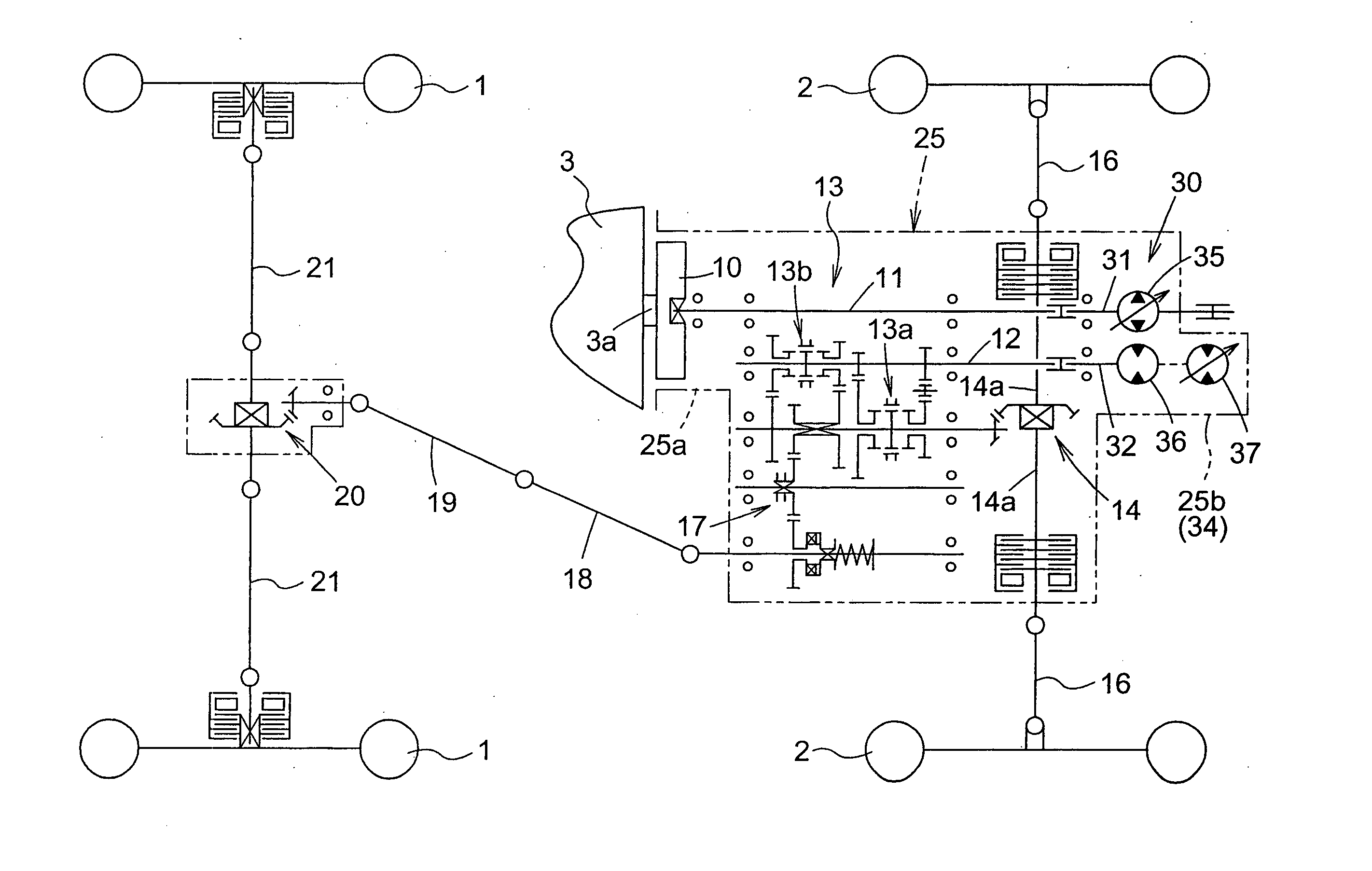
[0026] The power of the engine 3 is transmitted to the front and rear wheels 1, 2 by a traveling transmission unit shown in FIGS. 4 and 5. More particularly, an output from an output shaft 3a attached with a flywheel 10 located rearwardly of the engine 3 is transmitted via a rotational shaft 11 to an input shaft 3...


PUM


Abstract

A change-speed control system is provided for a utility vehicle having a stepless change-speed apparatus for speed-changing an engine output and transmitting the speed-changed output to a traveling unit. The system includes an engine speed governor for adjusting speed of the engine, an accelerator controller and a change-speed control linkage device for providing operative displacements in the stepless change-speed apparatus and the engine speed governor in association with an operation of the accelerator controller. The change-speed control linkage device sets an operation amount for the stepless change-speed apparatus and an operation amount for the engine speed governor in correlation with the operation amount of the accelerator controller, such that an acceleration ratio for the engine speed is greater than an acceleration ratio for the stepless change-speed apparatus until the engine reaches a predetermined speed and also the stepless change-speed apparatus reaches a predetermined speed.

Description

BACKGROUND OF THE INVENTION [0001] 1. Field of the Invention [0002] The present invention relates to a change-speed control system for a utility vehicle having a stepless change-speed apparatus for speed-changing an engine output and transmitting the speed-changed output to a traveling unit and also a change-speed control linkage device for linking a displacement of an accelerator controller with operations of an engine speed governor and the stepless change-speed apparatus, so that the stepless change-speed apparatus may be operated to an acceleration side in association with an operation of the engine speed governor to the acceleration side. [0003] 2. Description of the Related Art [0004] With such change-speed control system as described above, with an operation of the accelerator operation, both an adjustment of the engine speed and an adjustment of speed of the stepless change-speed apparatus can be made. A change-speed control system of this type is known from e.g. the Japanes...

Claims


Application Information

Patent Timeline
IPC IPC(8): B60K17/06B60W10/04B60W10/06B60W10/10B60W10/103F02D11/04F02D29/00F16H39/00F16H47/08F16H59/48
CPCB60W10/06B60W10/103B60W30/18027B60W30/18063Y10S180/90F16H57/04Y10T477/692Y10T74/2186Y10T74/19149B60W30/1819A01K61/80
Inventor NAKATANI, YASUNOBUHORIUCHI, YOSHIFUMI
Owner KUBOTA LTD
Why Eureka
Try Eureka