Applicator

Active Publication Date: 2005-03-24
TOKIWA CORP
View PDF8 Cites 21 Cited by
  • Summary
  • Abstract
  • Description
  • Claims
  • Application Information

AI Technical Summary

Benefits of technology

[0012] Furthermore, the application member has the following constitution. That is, the application member has a projection line on a plurality of places in a circumferential direction of a circumferential face of the recessed part. The projection line extends as much as a predetermined length from the bottom face side to the rear side of the recessed part and inwardly projects. The core member has a large diameter part and a groove part. The large diameter part is formed at the rear side from the projection part of the core member and fitted in the recessed part. The groove part extends as much as a predetermined length from the front end part to the rear side of the large diameter part and is fitted to the projection line. A second groove part is formed at the front end part of the groove part so as to be recessed at the further inside of the front end part and to reach the front end face of the large diameter part. The communication hole is opened at the second groove part by overlapping the inside face of the second groove part and an outer circumferential

Problems solved by technology

In the liquid cosmetic extrudable container, there is a problem that a hand, clothing or the like may become dirty since the liquid cosmetic may leak from the front end of the container due to an impact, a vibration or the like by falling or the like of the container, or a v

Method used


Image

  • Applicator
  • Applicator
  • Applicator

Examples


Embodiment Construction

[0034] Hereinafter, the suitable preferred embodiment of the applicator of the present invention is explained with referring to FIG. 1 to FIG. 10.

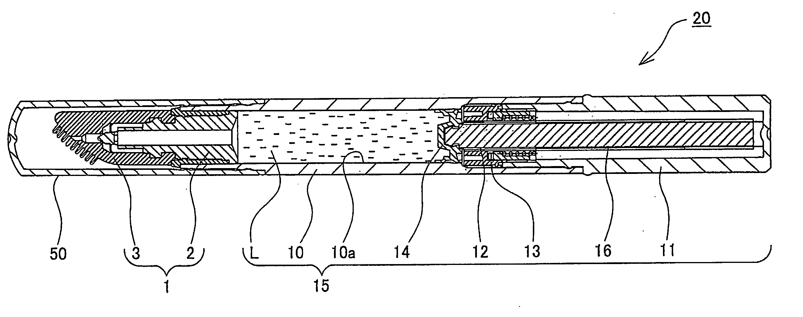
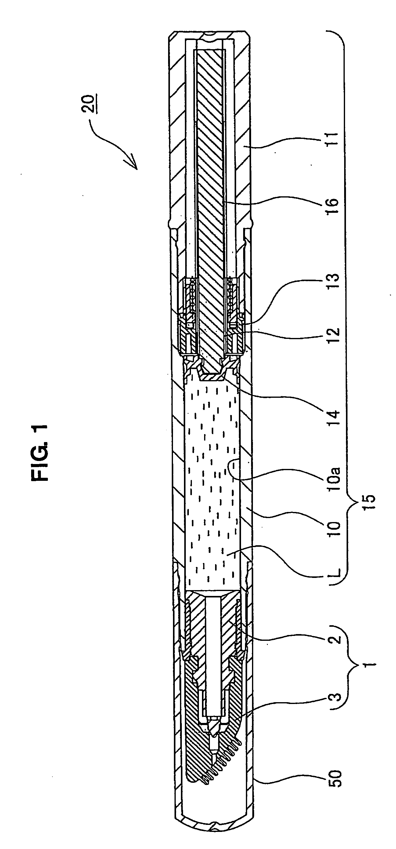
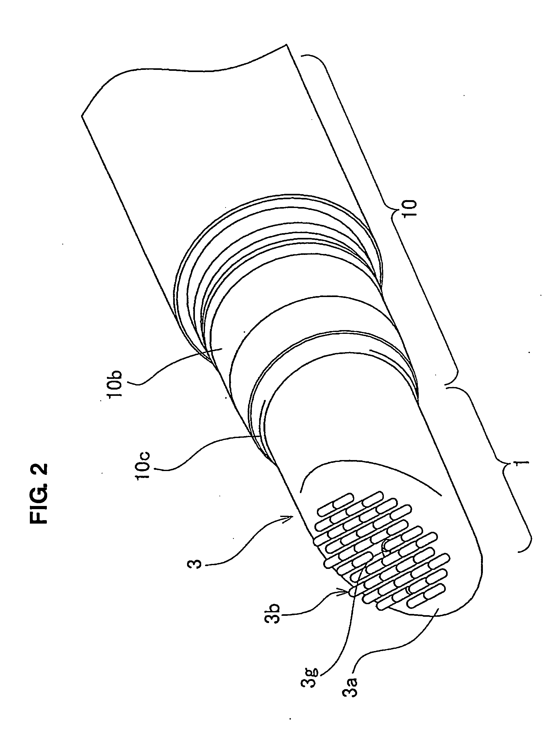
[0035]FIG. 1 to FIG. 10 are each figure showing the applicator according to the embodiment of the present invention. FIG. 1 is a longitudinal cross sectional view showing the liquid cosmetic extrudable container having an applicator according to an embodiment of the present invention. FIG. 2 is a perspective view of the end part including the applicator of the liquid cosmetic extrudable container. FIG. 3 and FIG. 4 are longitudinal cross sectional views where the cross sectional positions are 90° different respectively from the position of FIG. 2. FIG. 5 to FIG. 7 are each view particularly showing the core member constituting the applicator. FIG. 8 to FIG. 10 are views particularly showing the application member constituting the applicator. The applicator of the embodiment of the present invention is applied to the liquid cosmetic extrud...


PUM


Abstract

To prevent leakage, excessive delivery and stagnation of a liquid material applied by an applicator, the applicator comprises a core member 2 having a hole part 2a, a projection part 2f and a communication hole 2j, an application member 3 made of an elastic material having a delivery hole 3f, and an inside space 4 between the front end side of the core member 2 and the application member 3, and structured such that the liquid material flows to the delivery hole 3f through a roundabout way via the hole part 2a, the communication hole 2j and the inside space 4 to cause fluid resistance and that the front face of the projection part 2f is close to or in contact with the delivery hole 3f to control delivery of the liquid material.

Description

BACKGROUND OF THE INVENTION [0001] 1. Field of the Invention [0002] The present invention relates to an applicator for applying a liquid material filled therein. [0003] 2. Description of the Conventional Art [0004] Conventionally, the following applicator (for example, referring to Japanese Patent Laid Open No. 2000-262324) is known as a liquid cosmetic extrudable container from which the liquid cosmetic is extruded for use. That is, the applicator comprises a main body cylinder having inside a filling region, in which the liquid cosmetic is filled, and an operating cylinder mounted in the state of being relatively rotatable at a rear end part of the main body cylinder. In this applicator, the application can be carried out, by a piston arranged in the filling region being advanced when the main body cylinder and the operating cylinder are relatively rotated, the liquid cosmetic being extruded to an front end side by advancing of the piston, and the extruded liquid cosmetic being de...

Claims


Application Information

Patent Timeline
IPC IPC(8): A45D34/04A61M35/00B05C17/01B43K8/00B65D83/00
CPCA45D34/04B43K8/00B05C17/0133A61M35/003
Inventor TANI, YOSHIKAZU
Owner TOKIWA CORP
Why Eureka
Try Eureka