
Method and apparatus for modeling and analyzing MPLS and virtual private networks
a virtual private network and network model technology, applied in the field of computer networks, can solve the problems of inability to capture the relationship between a vpn routing and forwarding table (vrf) and a route target, and the network model that has been employed, and achieve the effect of capturing the relationship between a vpn routing and forwarding table and a route target, and a vpn. the problem of network model limitations
- Summary
- Abstract
- Description
- Claims
- Application Information
AI Technical Summary
Problems solved by technology
Method used
Image

Examples
Embodiment Construction
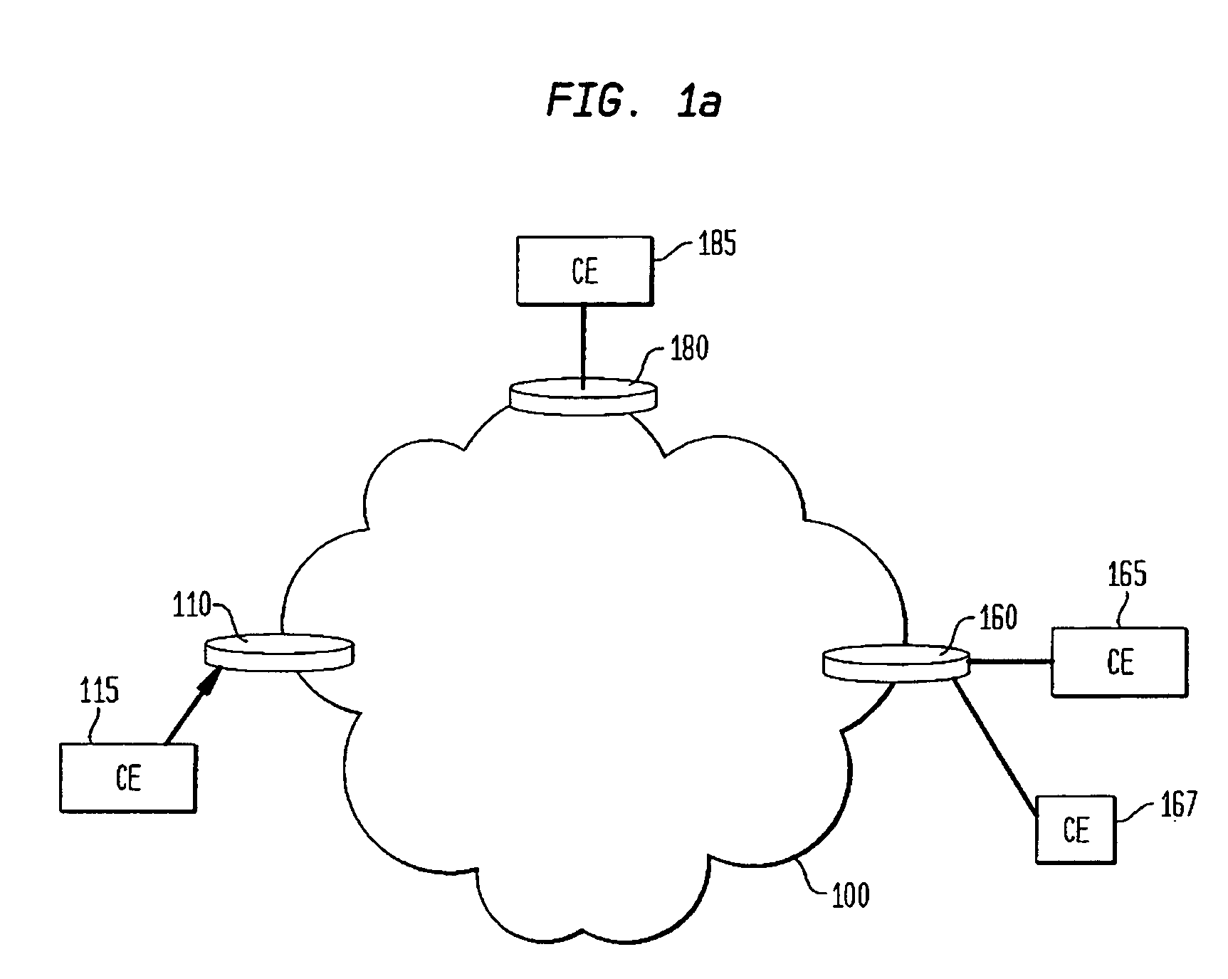
[0022]FIG. 1a illustrates an exemplary representation of a virtual private network 100 composed of components, referred to as provider edge routers (PE), 110, 160 and 180 that represent the means for providing information items to, and receiving information items from, network 100. Also shown are Customer Edge (CE) nodes or routers 115, 165, 167 and 185, which are in communication with corresponding provider edge nodes 110, 160 and 180. The CE nodes 115, 165, 167 and 185 represent are components or routers located at the customer premises that are directly connected, at either a network Layer 2 or Layer 3 level (of the OSI stack) to the ingress and egress provider edge routers 110, 160 and 180. Internal routers, which are not shown, are responsible for converting the packet or frame structure from the one used to communicate with CE routers 115, 165, 167, and 185 to the packet or frame structure used internally by an associated private network.
[0023] A CE router or node is typicall...
PUM
 Abstract
Description
Claims
Application Information