

Packaged orthodontic assembly with adhesive precoated appliances
- Summary
- Abstract
- Description
- Claims
- Application Information
AI Technical Summary
Benefits of technology
Problems solved by technology
Method used
Image

Examples
Embodiment Construction
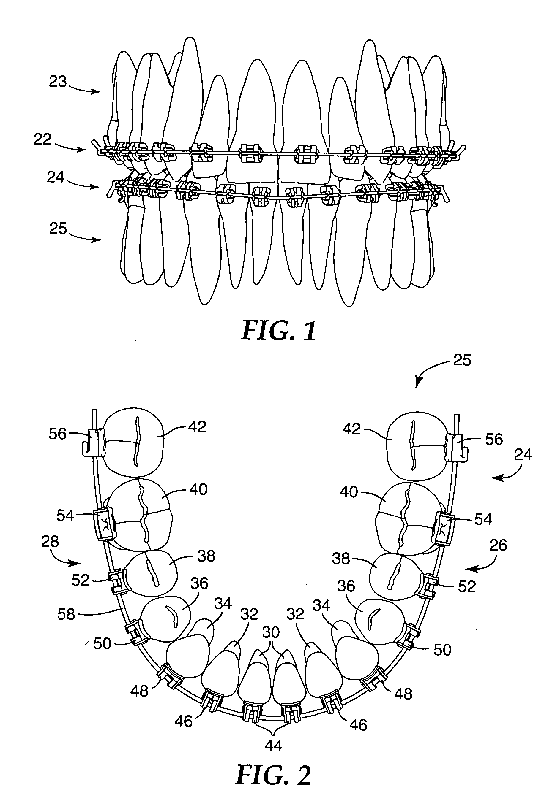
[0037]FIG. 1 illustrates an example of an oral cavity of an orthodontic patient that is undertaking orthodontic therapy. The patient has a first orthodontic brace 22 that is connected to the teeth of the upper dental arch 23 and a lower orthodontic brace 24 that is connected to the teeth of the lower dental arch 25. Each brace 22, 24 includes a set of orthodontic appliances along with an archwire that is received in slots of the appliances, as will be described in more detail below.
[0038]FIG. 2 is an enlarged view of the lower dental arch 25 along with the lower brace 24, looking in a downwardly direction toward the outer or occlusal tips of the teeth. The lower dental arch 25 includes a left quadrant 26 and a right quadrant 28. Each of the quadrants 26, 28 includes a central incisor tooth 30, a lateral incisor tooth 32, a cuspid tooth 34, a first bicuspid tooth 36 and a second bicuspid tooth 38. In addition, each of the quadrants 26, 28 includes a first molar tooth 40 and a second...
PUM
 Abstract
Description
Claims
Application Information