Yielding strata bolt

Inactive Publication Date: 2005-07-21
FERGUSSON JEFFREY ROBERT
View PDF10 Cites 52 Cited by
  • Summary
  • Abstract
  • Description
  • Claims
  • Application Information

AI Technical Summary

Benefits of technology

[0006] The object of the present invention is to provide a yielding cable bolt which is easy t

Problems solved by technology

Rock strata are liable to move as a result of various developments including mine-induced seismicity, the excavation of perimeter rock, minor earthquakes, and the like.
In general, regular rock bolts are insufficient to withstand such movement and snap.
As a consequence, in the event of gr

Method used


Image

  • Yielding strata bolt
  • Yielding strata bolt
  • Yielding strata bolt

Examples


second embodiment

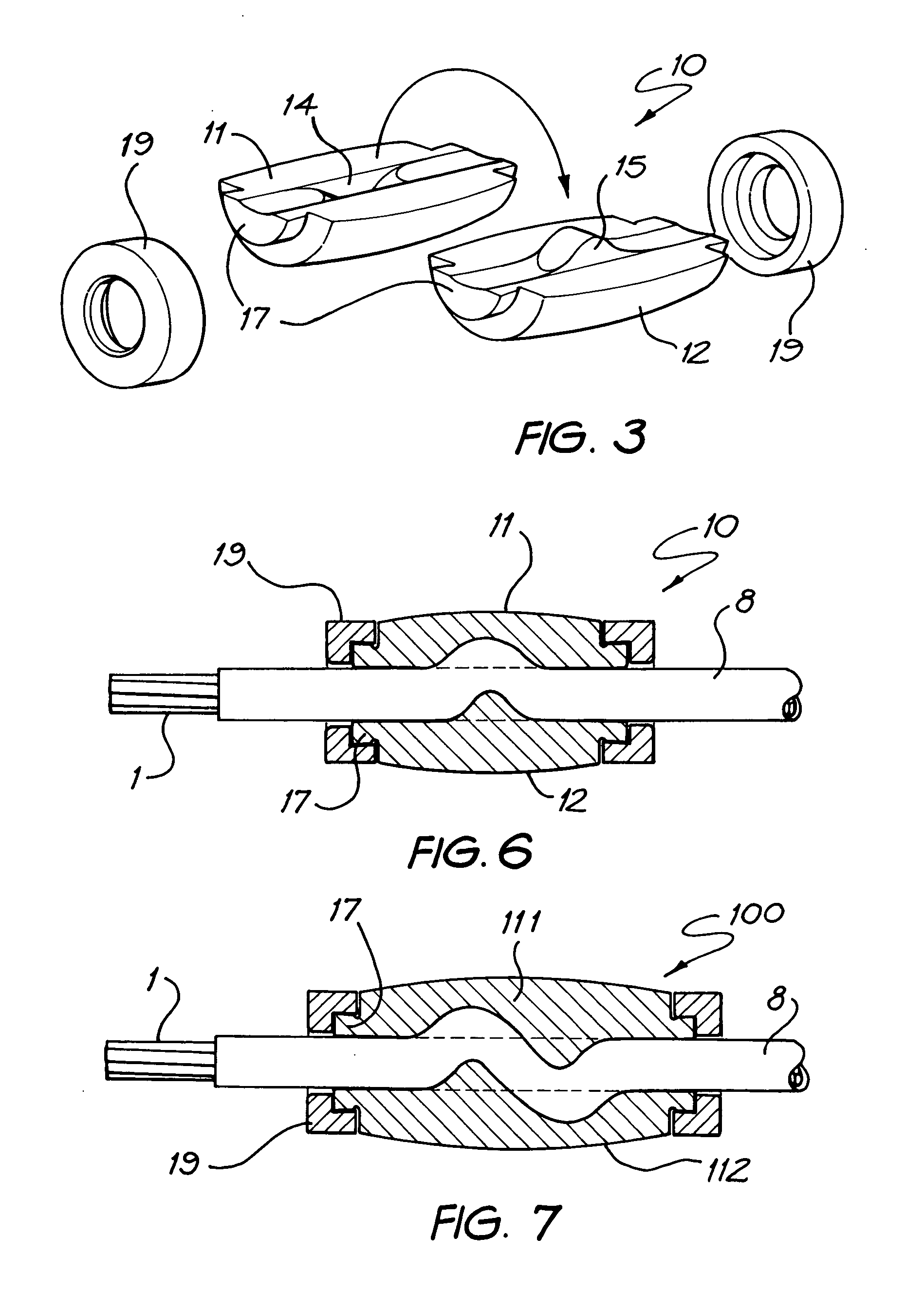
[0033]FIG. 7 illustrates the anchor 100 in which the keeper rings 19 are as before but each of the shells 111 and 112 is provided with a recess 114 and a protrusion 115. As will become apparent hereafter, the purpose of the anchor 100 of FIG. 7 is to provide a greater degree of work before the cable 1 can be passed there through.

first embodiment

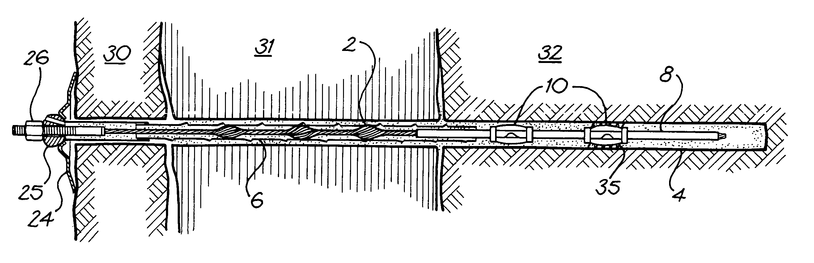
[0034] Turning now to FIG. 8, a yielding cable bolt 21 is illustrated. The tendon 22 of the bolt 21 is fabricated from the multi-strand steel cable 1 and the near end is provided with the threaded end fitting 23 which cooperates with a load plate 24, grout injector 25 and nut 26. The grout injector 25 works in the general manner described in the abovementioned Australian Patent No. 669,393 (WO 94 / 05900). In the embodiment illustrated in FIG. 8, a single anchor 10 is secured adjacent the free end of the bolt 21, however, in the embodiment illustrated in FIG. 9 a pair of spaced apart anchors 10 are so secured.

[0035] In the particular embodiment illustrated in FIG. 9, three strata 30, 31 and 32 are illustrated and strata 30 and 32 are relatively strong whereas stratum 31 is relatively weak and liable to movement. The tube 8 covers the cable 1 essentially throughout the stratum 32 but does not cover the cable 1 essentially throughout the strata 30 and 31. As a consequence, there is good...


PUM


Abstract

The present invention discloses a rock bolt having a tendon (1, 201) which is able to yield and thereby control movement of unstable rock strata into which the bolt is installed. The tendon has a portion which is provided with a grout slippage mechanism, preferably in the form of a tube (8) which surrounds the tendon. A two part grout anchor (10, 100, 200) is clamped to the tendon. The grout anchor is embedded in grout and is therefore essentially immovable. The tendon passing through the anchor is worked and thereby dissipates energy. The tendon can be either a multi-strand cable (1) or a solid bar (200). Various forms of anchor (10, 200) are disclosed with either complementary recess(es) (14) and protrusion(s) (15) or opposed protrusions (115) which form pinch point(s). A one piece grout anchor (300) is also disclosed.

Description

FIELD OF THE INVENTION [0001] The present invention relates to strata bolts and, in particular, to a yielding strata bolt intended to control the movement of unstable rock strata into which the bolt is installed. The tendon of the bolt can either be a solid rod or a flexible cable. BACKGROUND ART [0002] Rock strata are liable to move as a result of various developments including mine-induced seismicity, the excavation of perimeter rock, minor earthquakes, and the like. Some such movements are termed “rock bursts”. [0003] In general, regular rock bolts are insufficient to withstand such movement and snap. In the past various proposals have been made. One such proposal is the so called DURABAR or DURABOLT (South African Patent No. 94 / 2177) invented by D Ortlepp which provides a heavy solid steel bar with a wriggle-like deformation. The bar is grouted in place at installation. As a consequence, in the event of ground movement, the deformed portion of the bar pulls through the grout and...

Claims


Application Information

Patent Timeline
IPC IPC(8): E21D21/00
CPCE21D21/0026E21D21/008E21D21/0033
Inventor FERGUSSON, JEFFREY ROBERT
Owner FERGUSSON JEFFREY ROBERT
Why Eureka
Try Eureka